
A circular waveguide dual-frequency common-aperture antenna based on structural multiplexing

A circular waveguide and common aperture technology, applied in the field of circular waveguide dual-frequency common aperture antennas, can solve the problems of low utilization rate of antenna apertures and insufficient isolation between antennas, and achieve various feeding forms, improved isolation, and utilization of antenna apertures. rate increase effect

Active Publication Date: 2021-02-05
UNIV OF ELECTRONICS SCI & TECH OF CHINA
View PDF8 Cites 0 Cited by
  • Summary
  • Abstract
  • Description
  • Claims
  • Application Information

AI Technical Summary

Problems solved by technology

[0006] The purpose of the present invention is to propose a circular waveguide based on structural multiplexing for the problems that the frequency ratio is not even and it is difficult to use the traditional common-aperture layout, and the antenna aperture utilization rate caused by the traditional layout method is low, and the isolation between antennas is insufficient. Dual-frequency common-aperture antenna; the present invention is based on the concept of structural multiplexing, and completes the design requirements of two frequency band antennas

Method used


Image

  • A circular waveguide dual-frequency common-aperture antenna based on structural multiplexing
  • A circular waveguide dual-frequency common-aperture antenna based on structural multiplexing
  • A circular waveguide dual-frequency common-aperture antenna based on structural multiplexing

Examples


Embodiment Construction

[0019] The present invention will be further elaborated below in conjunction with the accompanying drawings and embodiments.

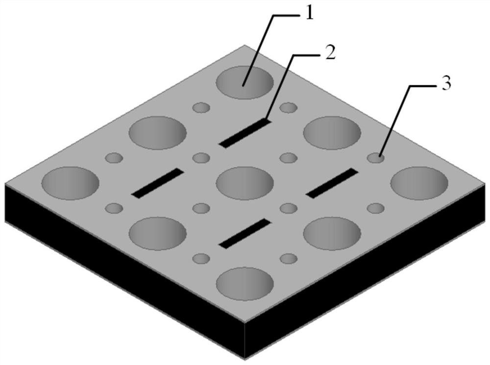
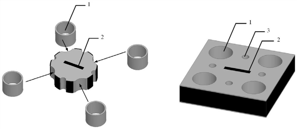
[0020] This embodiment provides a circular waveguide dual-frequency co-aperture array antenna based on structural multiplexing, and its 2×2 array is as follows figure 1 As shown, wherein the antenna unit includes: 4 circular waveguide antennas 1, 4 auxiliary structures, that is, 1 cavity-backed slot antenna; the working frequency ratio of the antenna in this embodiment can be an even or non-even ratio, and The shaped waveguide antenna and the cavity-backed slot antenna are integrated by utilizing the special structure, without additional increase in the antenna aperture area, and the high-pass characteristics of the circular waveguide and its non-open radiation structure improve the isolation between the two frequency antennas.

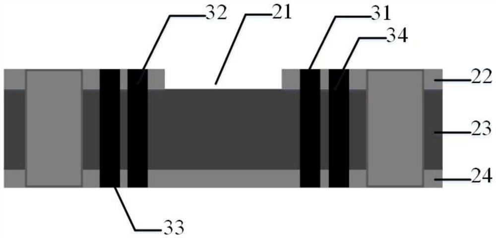
[0021] In this embodiment, the structure of the antenna unit is as follows figure 2 shown; including: a lower metal copper...


PUM


Abstract

The invention belongs to the technical field of common-aperture antennas, and provides a circular waveguide dual-frequency common-aperture antenna based on structural multiplexing, which is used to overcome the low aperture utilization rate of the traditional dual-frequency common-aperture antenna array, the frequency ratio is mostly an even ratio and the The problem of low antenna isolation. The invention utilizes the metal-enclosed structure of the cylindrical waveguide, uses four circular waveguide antennas and the auxiliary metallized through holes between them to form the side wall of the cavity-backed antenna, and then opens a radiation gap at the center of the cavity to form a cavity-backed gap An antenna; and, by adjusting the distance between the circular waveguides, the antenna design with a non-even ratio of the frequency ratio can be carried out; the antenna layout under the structure multiplexing of the present invention does not generate additional aperture area, and the antenna aperture utilization rate is improved; and, Utilizing the high-pass characteristics of the circular waveguide and its non-open radiation structure, the isolation between high and low frequency antennas can be improved.

Description

technical field [0001] The invention belongs to the technical field of common-aperture antennas, in particular to a circular waveguide dual-frequency common-aperture antenna based on structural multiplexing. Background technique [0002] Traditional co-aperture antennas can place multiple antennas with multiple frequency bands, multiple polarizations, and multiple functions in the same radiation aperture, thereby greatly improving the aperture utilization of the system. However, as the millimeter-wave frequency band becomes the main frequency band used in the new generation of wireless technology, multiple high-frequency band antennas also face the need for common-aperture integration, and with the increase in frequency and the expansion of the frequency ratio range, the existing common-aperture method is difficult to achieve The antenna layout with non-even frequency ratio, the traditional layout method leads to low aperture utilization, and it is difficult to meet the need...

Claims


Application Information

Patent Timeline
Patent Type & Authority Patents(China)
IPC IPC(8): H01Q21/24H01Q21/06H01Q13/18H01Q13/10H01Q1/52H01Q1/50H01Q1/38
CPCH01Q1/38H01Q1/50H01Q1/521H01Q13/106H01Q13/18H01Q21/061H01Q21/064H01Q21/24
Inventor 程钰间丁嫣然夏飞扬赵凡刘彦柏航樊勇张波林先其宋开军赵明华
Owner UNIV OF ELECTRONICS SCI & TECH OF CHINA
Learn More