Heat dissipation device and lighting device

A technology for radiating components and fins, applied in the field of heat dissipation, can solve the problems of poor heat dissipation, inability to install high-power lamps, and failure to achieve the required heat dissipation effect, so as to improve the heat dissipation effect, increase the effective service life, and improve the convection. The effect of heat dissipation

Active Publication Date: 2019-08-09
东莞市闻誉实业有限公司
View PDF8 Cites 1 Cited by
  • Summary
  • Abstract
  • Description
  • Claims
  • Application Information

AI Technical Summary

Problems solved by technology

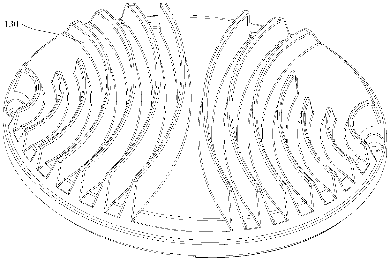
[0002] like figure 1 As shown, in the die-casting light-emitting diode (LED, Light Emitting Diode) heat dissipation product, the heat sinks 110 are arranged in a straight line in the same direction or connected to the tail end in the same shape; The maximum effect takes away the heat, which leads to unsatisfactory heat dissipation. The heat dissipation of the lights installed inside is not good, the life of the lights is not long, and high-power lights cannot be installed.
[0003] The heat dissipation effect of the die-cast heat sink products arranged in regular directions on the market is not very good, especially in the natural heat dissipation environment without fans, resulting in some high-power lamps not meeting the requirements after being installed inside. The heat dissipation effect, and the heat dissipation effect is not good, resulting in the life of the lamp is far less than the time required by the design

Method used


Image

  • Heat dissipation device and lighting device
  • Heat dissipation device and lighting device
  • Heat dissipation device and lighting device

Examples


Embodiment Construction

[0035] In order to make the above-mentioned purpose, features and advantages of the present application more obvious and understandable, the specific implementation manners of the present application will be described in detail below in conjunction with the accompanying drawings. In the following description, numerous specific details are set forth in order to provide a thorough understanding of the application. However, the present application can be implemented in many other ways different from those described here, and those skilled in the art can make similar improvements without departing from the connotation of the present application, so the present application is not limited by the specific embodiments disclosed below.

[0036] It should be noted that when an element is referred to as being “fixed on” or “disposed on” another element, it may be directly on the other element or there may be an intervening element. When an element is referred to as being "connected to" a...


PUM


Abstract

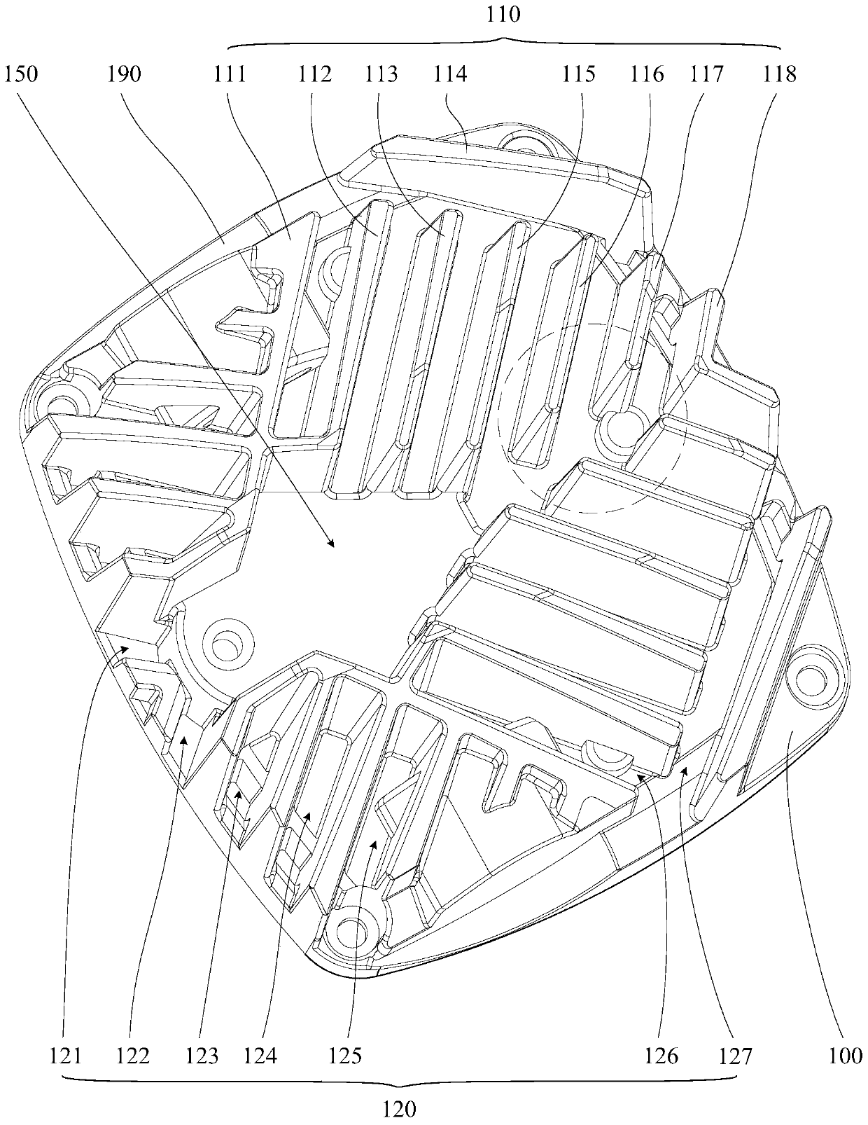
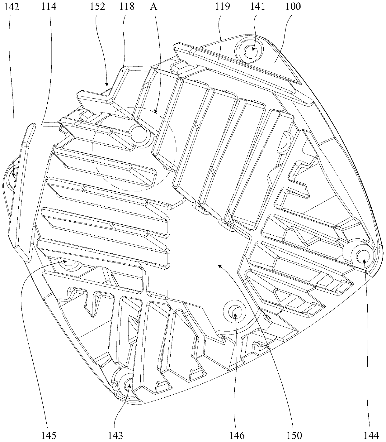
The invention relates to a heat dissipation device and a lighting device. The heat dissipation device comprises a heat dissipation body and a plurality of heat dissipation fin bodies located on the heat dissipation body. Each heat dissipation fin body is provided with at least three air channels and at least one wind shielding position, and an air channel opening is formed at the edge position ofeach radiating fin body; at least one wind shielding position is arranged at the edge position of the heat dissipation body, and at least one air channel is arranged towards the at least one wind shielding position. The air channels and the wind shielding positions are designed to form the heat dissipation fin bodies which are arranged irregularly, so that air flow is forcedly reversed at the windshielding position, on one hand, the contact time of the air flow is prolonged to improve the heat conduction effect between the solid heat dissipation fin bodies and gaseous air, on the other hand,air can be fully utilized to further improve the convectional heat dissipation effect on the basis of solid-gas conduction, accordingly the effect of bringing away the heat on the heat dissipation device as soon as possible is achieved, and thus the heat dissipation effect of an object with heat to be dissipated is improved. The real effective service life of an LED lamp is prolonged for the LEDlamp.

Description

technical field [0001] The present application relates to the field of heat dissipation, in particular to heat dissipation devices and lighting equipment. Background technique [0002] Such as figure 1 As shown, in the die-casting light-emitting diode (LED, Light Emitting Diode) heat dissipation product, the heat sinks 110 are arranged in a straight line in the same direction or connected to the tail end in the same shape; The maximum effect takes away the heat, resulting in unsatisfactory heat dissipation. The heat dissipation of the lamps installed inside is not good, the life of the lamps is not long, and high-power lamps cannot be installed. [0003] The heat dissipation effect of the die-cast heat sink products arranged in regular directions on the market is not very good, especially in the natural heat dissipation environment without fans, resulting in some high-power lamps not meeting the requirements after being installed inside. The heat dissipation effect, and th...

Claims


Application Information

Patent Timeline
Patent Type & Authority Applications(China)
IPC IPC(8): F21K9/20F21V29/75F21V29/67F21Y115/10
CPCF21V29/673F21V29/75F21V29/83F21K9/20F21Y2115/10
Inventor 叶伟炳陈晓健
Owner 东莞市闻誉实业有限公司
Why Eureka
Try Eureka