
Pressure control device of micro-pressure electric cooker and micro-pressure electric cooker

A pressure control, micro-piezoelectric technology, applied in pressure cookers, cooking utensils, household appliances, etc., can solve problems such as difficulty in ensuring the taste of cooked meals, failure to achieve intermittent exhaust, poor user experience, etc., and achieve a state of pressure. Intuitive and clear, reducing waiting time and satisfying experience requirements

Pending Publication Date: 2019-08-09
DEA GENERAL AVIATION HLDG CO LTD
View PDF0 Cites 7 Cited by
  • Summary
  • Abstract
  • Description
  • Claims
  • Application Information

AI Technical Summary

Problems solved by technology

The micro-pressure rice cooker is popular in the market because of its soft cooking. The micro-pressure rice cooker will generate a certain pressure during the heating process. The lid cannot be opened immediately after cooking. It is necessary to exhaust the body of the pot. It takes a long time to open the lid, and the pressure inside the cooker is constant when cooking, so intermittent exhaust cannot be realized, and it is difficult to ensure the taste of the food in the cooker, resulting in poor user experience

Method used


Image

  • Pressure control device of micro-pressure electric cooker and micro-pressure electric cooker
  • Pressure control device of micro-pressure electric cooker and micro-pressure electric cooker
  • Pressure control device of micro-pressure electric cooker and micro-pressure electric cooker

Examples


Embodiment Construction

[0029] The present application will be further described below in conjunction with the accompanying drawings and specific embodiments.

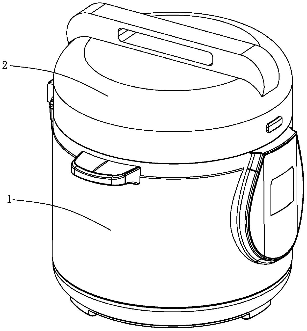
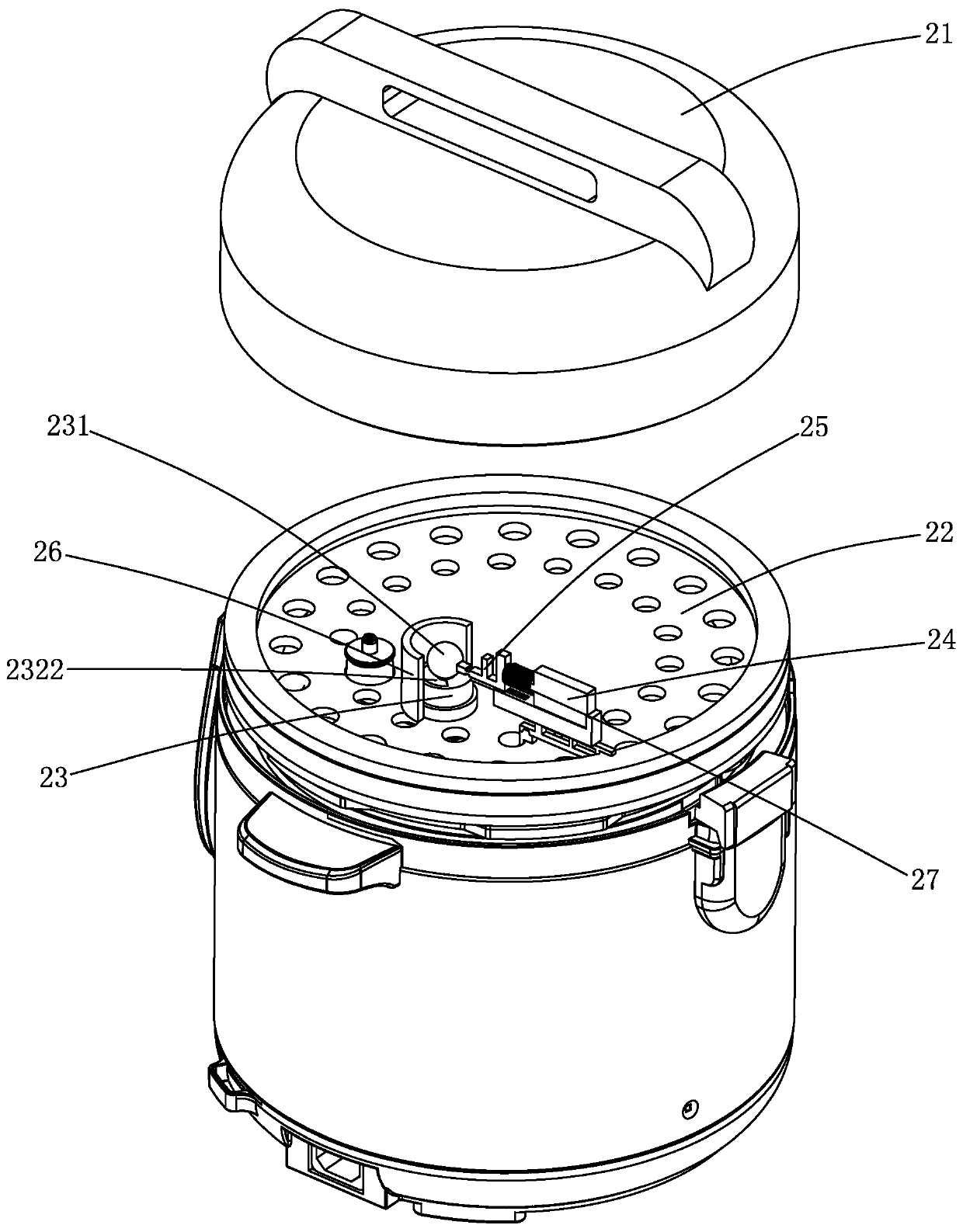
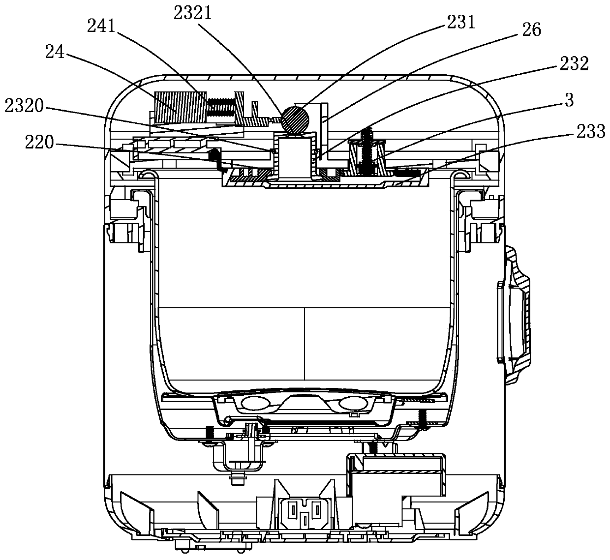
[0030] Please see attached figure 1 to attach Figure 4 , a micro-piezoelectric rice cooker, comprising a pot body 1 and a pot cover 2 hinged on the pot body, the pot cover includes an outer cover 21 and an inner cover 22 arranged on the lower side of the outer cover, the inner cover 22 is provided with a pressure control device, It includes a solenoid valve 24 and a pressing member 25 controlled by the solenoid valve, and also includes a pressure control assembly 23 for controlling the pressure in the pot body, and the pressure control assembly includes a movable steel ball arranged in the lid of the electric rice cooker 231 and the steel ball support seat 232 that is used to support the steel ball on the pot cover, the top of the steel ball support seat is provided with an exhaust hole 2321, and the top surface of the steel ball support se...


PUM


Abstract

The invention relates to the technical field of electric cookers, in particular to a pressure control device of a micro-pressure electric cooker and the micro-pressure electric cooker. The pressure control device comprises an electromagnetic valve and an ejecting piece controlled by the electromagnetic valve, and further comprises a pressure control assembly. The pressure control assembly comprises a movable steel ball and a steel ball supporting base arranged on a cooker cover and used for supporting the steel ball. An exhaust hole is formed in the top of the steel ball supporting base. A concave site downwards indented, matched with the steel ball and used for placing the steel ball is arranged on the top end face of the steel ball supporting base. The exhaust hole is arranged at the bottom of a concave surface and communicated with the interior of a cooker body. A stop piece is arranged on the cooker cover. A gap for the steel ball to move is formed between the stop piece and the steel ball supporting base. When the electromagnetic valve is in a turned-off state, the ejecting piece ejects the steel ball so that the steel ball can be disengaged from the exhaust hole to abut against the stop piece. By arranging the pressure control device on the cooker cover of the electric cooker, the pressure in the cooker body can be effectively controlled, the electric cooker is convenientto uncover after cooking rice, there is no need to wait for the natural cooling of the cooker body, and waiting time is shortened.

Description

[0001] 【Technical field】 [0002] The present application relates to the technical field of electric rice cookers, in particular to a pressure control device for a micro-piezoelectric rice cooker and the micro-piezoelectric rice cooker. [0003] 【Background technique】 [0004] With the development of rice cooker technology, the control technology of rice cooker has also gone through several important stages, first is mechanical control, then electronic control, microcomputer control, and then the electromagnetic and micro-pressure rice cooker that will become the mainstream of the market. The micro-pressure rice cooker is popular in the market because of its soft cooking. The micro-pressure rice cooker will generate a certain pressure during the heating process. The lid cannot be opened immediately after cooking, and the body needs to be exhausted. After the body cools down naturally It takes a long time to open the lid, and the pressure in the body of the pot is constant when ...

Claims


Application Information

Patent Timeline
Patent Type & Authority Applications(China)
IPC IPC(8): A47J27/08A47J27/09
CPCA47J27/08A47J27/0802A47J27/09
Inventor 董守才欧伟成
Owner DEA GENERAL AVIATION HLDG CO LTD
Learn More