Metal extrusion molding machine

A metal extrusion and molding machine technology, applied in the field of metal extrusion molding machines, can solve the problems of difficulty in reaching a molten state, large axial force, and unsuitable for continuous metal extrusion process.

Inactive Publication Date: 2019-08-06
何志炜
View PDF0 Cites 0 Cited by
  • Summary
  • Abstract
  • Description
  • Claims
  • Application Information

AI Technical Summary

Problems solved by technology

[0005] First of all, the melting of metal requires more heat. This kind of heating only depends on the barrel, and the heating efficiency is very low. It takes a very long time for the metal to reach the molten state. The subsequent continuous production after the heat engine also requires strong thermal support to melt the metal in time. , but the above-mentioned extruder only has a single heating from the outside to the inside, and the metal material close to the screw is difficult to reach the molten state before sending out
[0006] Secondly, there are also extruders with screw heating function, but this kind of extruder equipped with heating screw is only suitable for plastic extrusion production, not suitable for metal continuous extrusion process
The heating rod inside the screw of this extruder rotates together with the screw, so that the effect of simultaneous internal and external heating of the material between the barrel and the screw can be achieved, and the efficiency of heating and melting can be comprehensively improved, but the current structure generates heat After the rod is inserted into the screw, it is fixedly installed with the screw. When the screw rotates to extrude the material, the heating rod can only rotate synchronously with the screw, resulting in a rather complicated conductive structure at the end of the screw. If the brush is used to conduct electricity, the contact There is always wear and tear in the conductive brush of the traditional type, and it is necessary to monitor the wear of the brush frequently and replace it in time, which increases the maintenance cost of the extruder
In addition, compared with plastics, metal materials have higher melting temperature and poor material fluidity, and the axial force generated during the rotation of the screw is very large. The above-mentioned extruder cannot bear such a large axial force, so there is no available in the industry at present. A special metal extrusion molding machine that realizes uninterrupted and continuous extrusion production of metal
[0007] Therefore, the current metal material delivery molding can only be formed by piston-type push extrusion molding. This piston-type push-extrusion molding can only be produced intermittently. Every time a push-extrusion production is completed, it is necessary to wait for the piston to reset and start. Wait for the metal to reach the molten state before proceeding to the next push extrusion molding, which cannot achieve continuous and uninterrupted extrusion

Method used


Image

  • Metal extrusion molding machine
  • Metal extrusion molding machine
  • Metal extrusion molding machine

Examples


Embodiment Construction

[0019] The technology will be further described below in conjunction with the accompanying drawings.

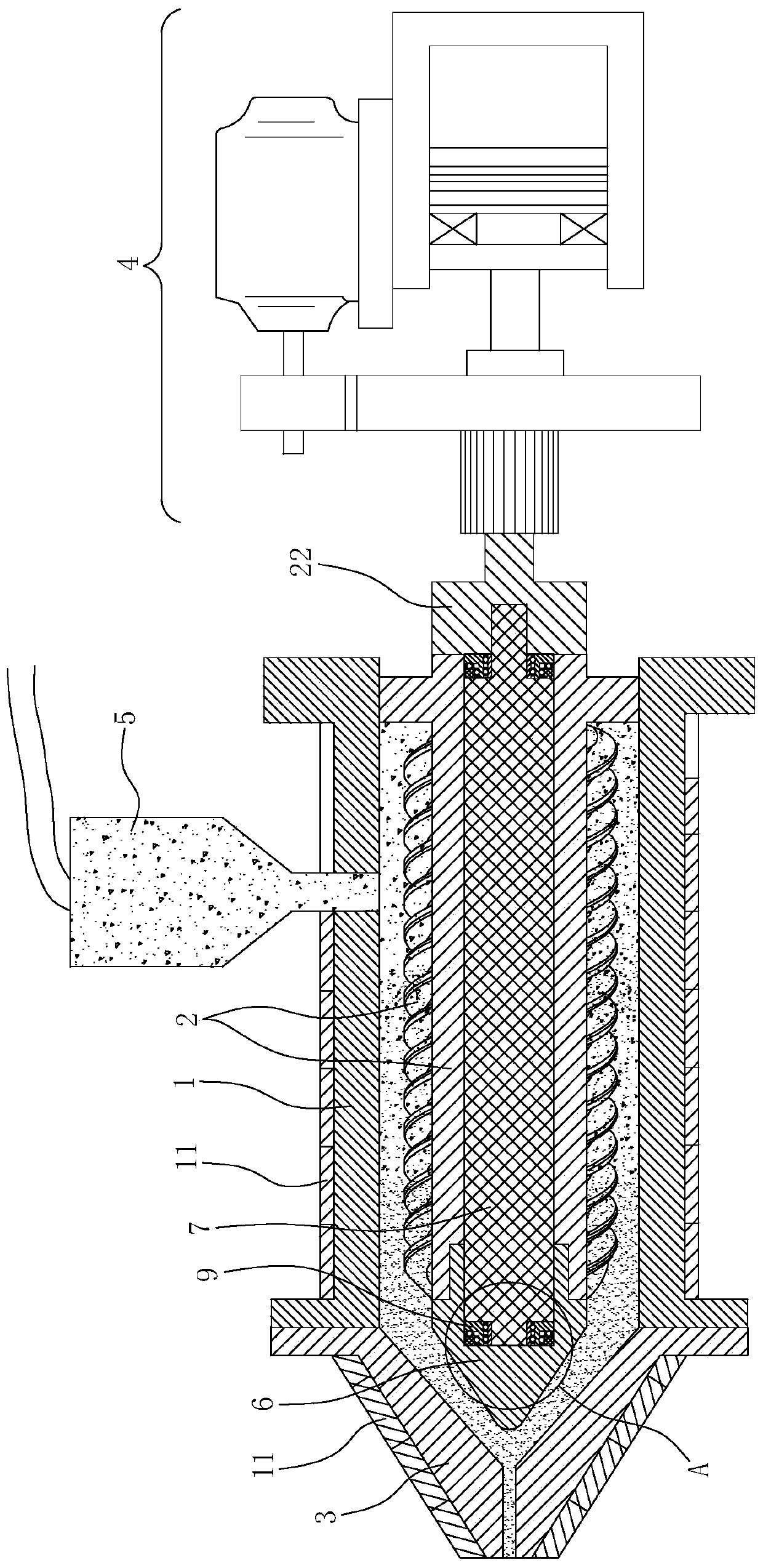
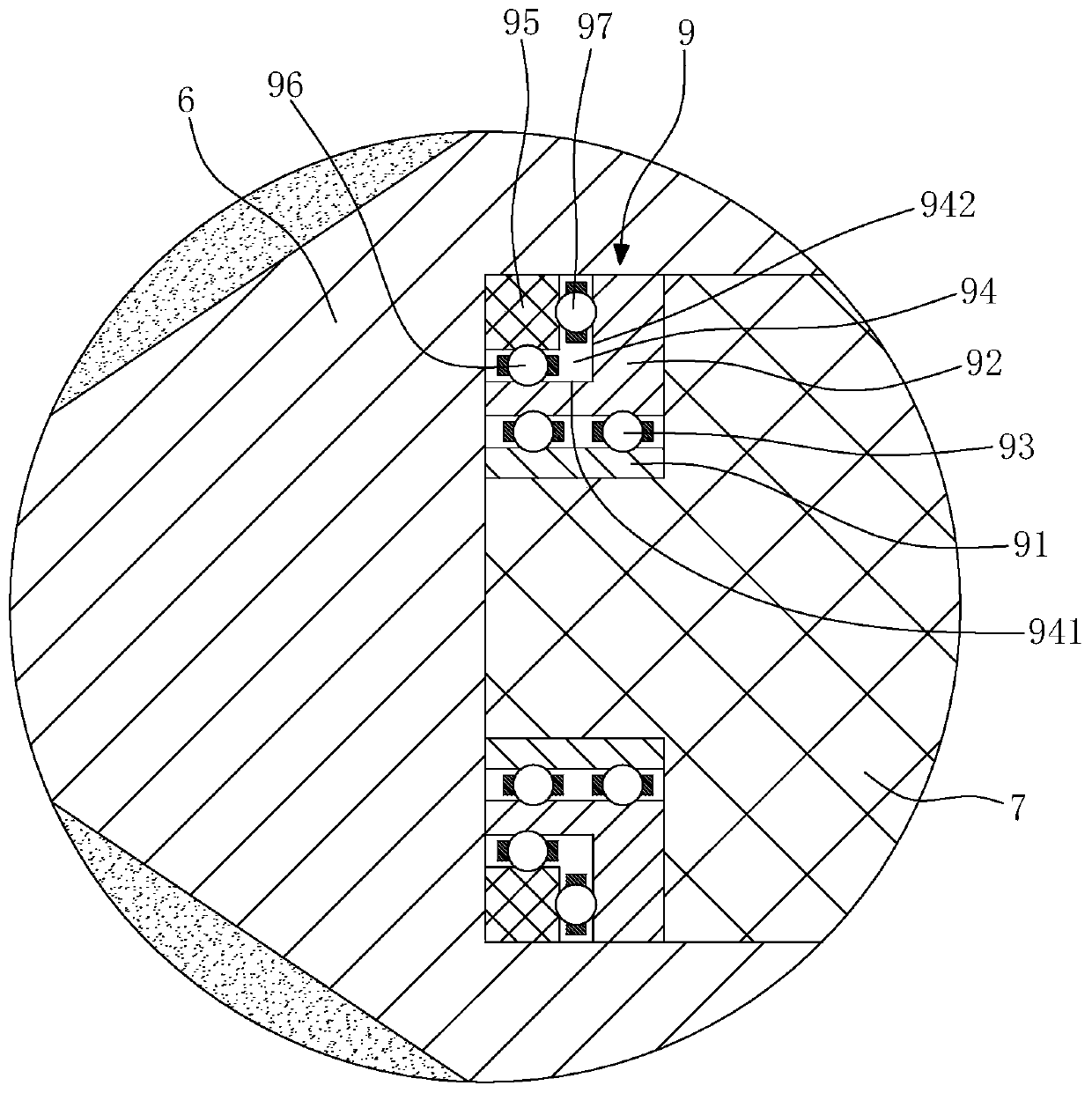
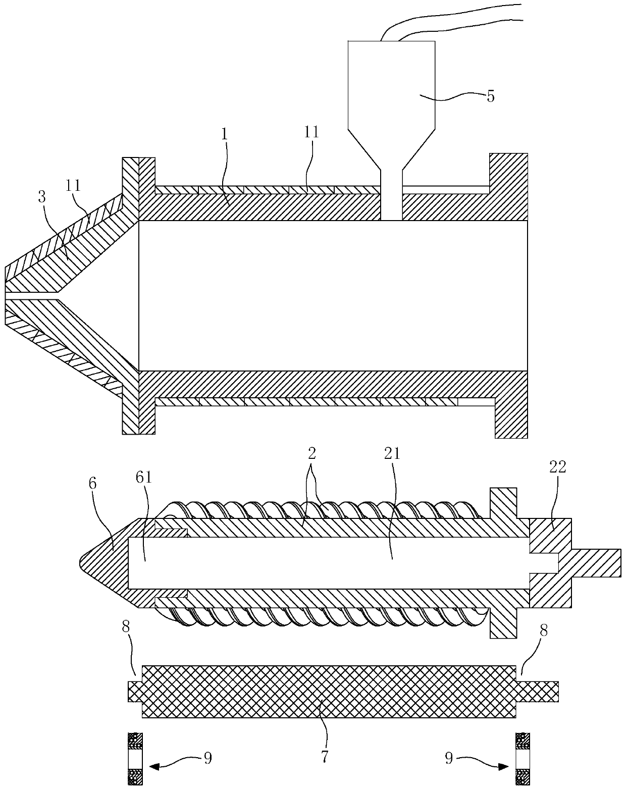
[0020] The metal extrusion molding machine of this embodiment includes a barrel 1, a screw rod 2, a die head 3 and a power system 4, and a heating element 11 is arranged on the outer wall of the barrel 1 and the die head 3, and the screw rod 2 is inserted into the barrel 1 Inside, the die head 3 is installed at the front end of the barrel 1, and a feeding funnel 5 is arranged above the barrel 1. The power system 4 drives the screw 2 to rotate, and the screw 2 is a hollow structure. The shuttle 6 is a hollow structure, and a heating rod 7 is inserted in the inner cavity 21 of the screw rod 2. A stepped concave ring 8 is formed on the front end and the rear end of the heating rod 7, and two-way The force bearing 9 is provided with a T-shaped end cover 22 at the end of the screw rod 2. The T-shaped end cover 22 is against the two-way force bearing 9. The tail section of the T-sh...


PUM


Abstract

The invention discloses a metal extrusion forming machine. The metal extrusion forming machine is characterized in that a heating element is arranged on the outer wall of a gun barrel, a screw rod isinserted into the gun barrel, a mold head is arranged at the front end of the gun barrel, a feeding hopper is arranged above the gun barrel, a power system drives the screw rod to rotate, the screw rod and a flow guide shuttle are of a hollow structure, the flow guide shuttle is arranged at the front end of the screw rod, a heating rod is inserted into the inner cavity of the screw rod, the frontend and the rear end of the heating rod are both provided with two-way stress bearings, the front end of the heating rod extends into a flow guide shuttle cavity, each two-way stress bearing comprisesan inner ring, an outer ring and first balls, the inner rings are arranged in the outer rings in a sleeved mode, the plurality of first balls are arranged, the first balls are arranged between the inner rings and the outer rings, an outer convex annular stepped structure is formed on the outer periphery surface of each outer ring, an auxiliary pressing ring is arranged at each annular step, a plurality of second balls are arranged at intervals between the auxiliary pressing rings and stepped planes of the annular steps along the circumference, and a plurality of third balls are arranged between the auxiliary pressing rings and stepped vertical surfaces at intervals along the circumference.

Description

[0001] Technical field: [0002] The invention relates to a metal extrusion molding machine. [0003] Background technique: [0004] For a long time, the plastic extruder relies on the heating wire on the outer wall of the barrel to heat and melt the material in the barrel, and uses the rotation of the screw inside the barrel to push the molten material out of the mold mouth, that is, the barrel is only responsible for heating , the screw is only responsible for pushing the material forward. But the extruder with this structure is not suitable for metal extrusion process. [0005] First of all, the melting of metal requires more heat. This kind of heating only depends on the barrel, and the heating efficiency is very low. It takes a very long time for the metal to reach the molten state. The subsequent continuous production after the heat engine also requires strong thermal support to melt the metal in time. , but the above-mentioned extruder only has a single heating from th...

Claims


Application Information

Patent Timeline
IPC IPC(8): B21C23/21B21C29/04
CPCB21C23/21B21C29/04
Inventor 何志炜
Owner 何志炜
Why Eureka
Try Eureka