
Charging pile for new energy automobile

A technology of new energy vehicles and charging piles, applied in electric vehicle charging technology, charging stations, electric vehicles, etc., can solve the problems of inconvenient cleaning, easy to adhere to dust, etc., and achieve the effect of good cleaning function

Active Publication Date: 2019-08-06
深圳全民通节能科技有限公司
View PDF9 Cites 5 Cited by
  • Summary
  • Abstract
  • Description
  • Claims
  • Application Information

AI Technical Summary

Problems solved by technology

[0005] The purpose of the present invention is to provide a new energy vehicle charging pile that can be automatically cleaned according to the frequency of use to solve the problem that the charging pile is exposed to the outside for a long time, is easy to adhere to dust, and is not easy to clean.

Method used


Image

  • Charging pile for new energy automobile
  • Charging pile for new energy automobile
  • Charging pile for new energy automobile

Examples


Embodiment 1

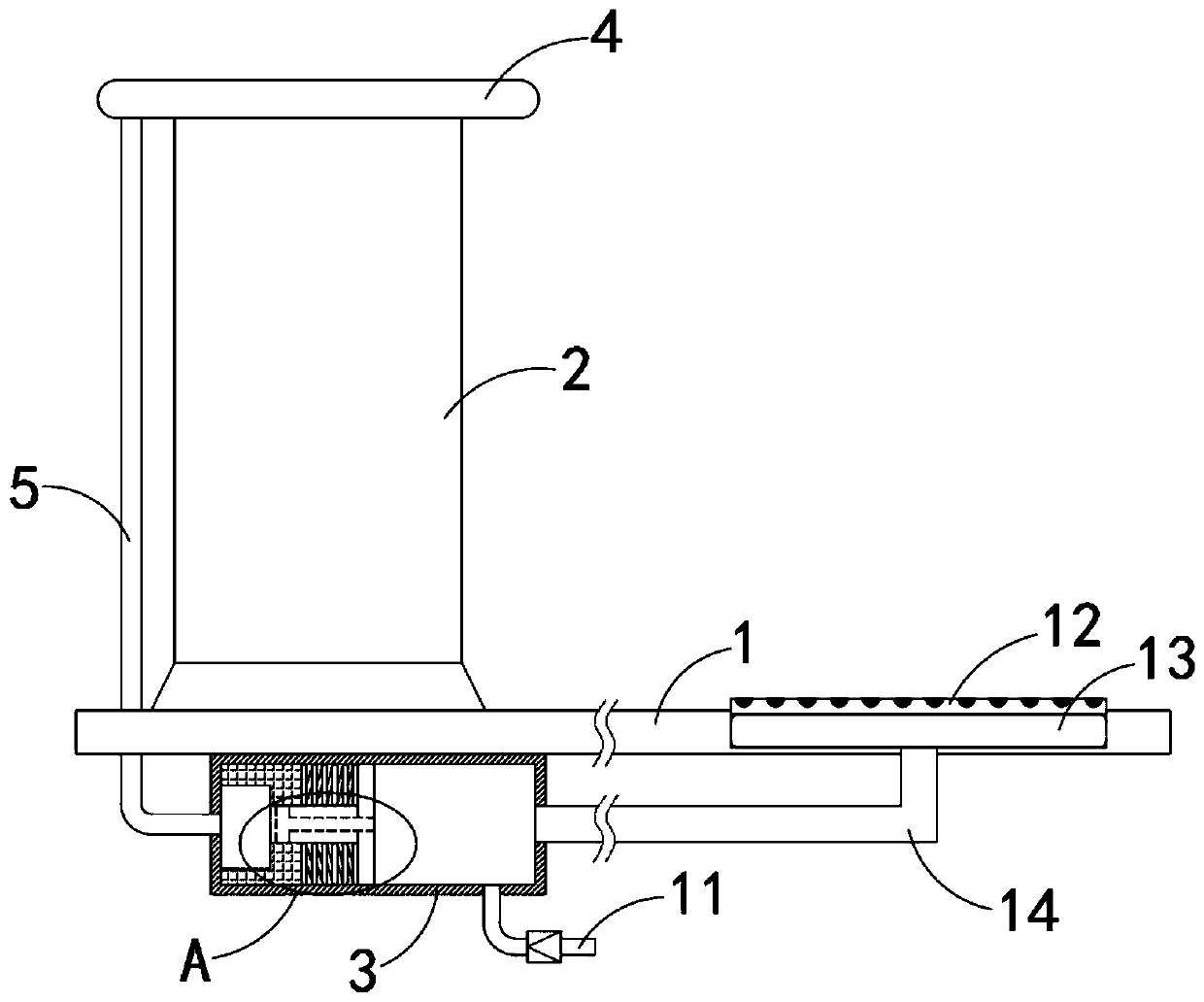
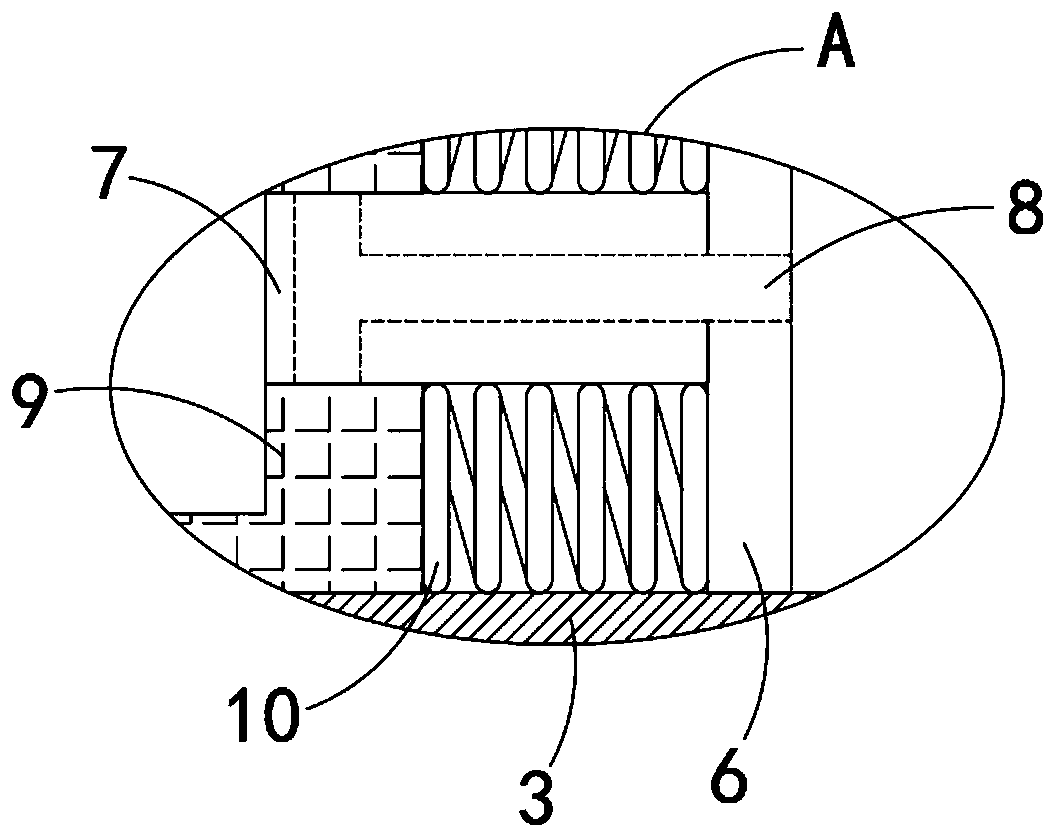
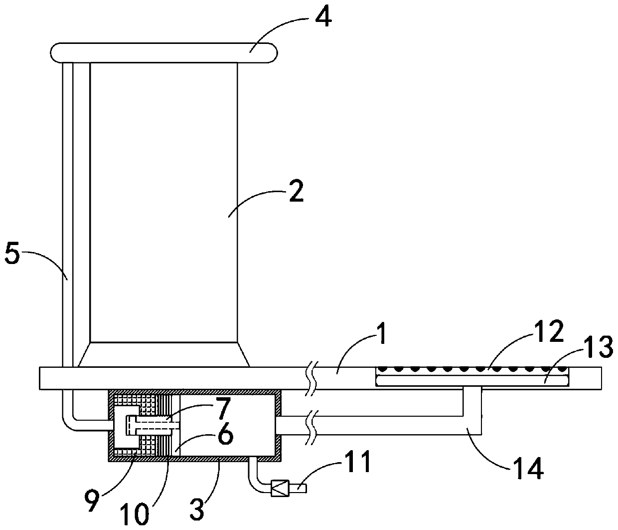
[0023] Such as Figure 1-4 As shown, a new energy vehicle charging pile includes a bottom plate 1, a charging pile body 2 is installed on the upper end of the bottom plate 1, a water storage tank 3 is arranged below the bottom plate 1, and an annular water outlet pipe 4 is fixedly connected to the upper end of the charging pile body 2. A plurality of water spray holes 15 are evenly arranged on the inner ring side wall of the annular water outlet pipe 4, and the annular water outlet pipe 4 is connected with the water storage tank 3 through the communication pipe 5, and the movable plate 6 is slidably connected in the water storage tank 3, and the movable plate 6 The side wall is fixedly connected with a piston block 7, the piston block 7 is provided with a permeable hole 8, the water inlet end of the permeable hole 8 is arranged on the side wall of the movable plate 6, and the water outlet end of the permeable hole 8 is arranged on the periphery of the piston block 7 on the sid...

Embodiment 2

[0027] Such as Figure 5 As shown, the difference between this embodiment and Embodiment 1 is that a guide ring 16 is sealed and rotated on the inner wall of the annular outlet pipe 4, and a plurality of water spray holes 15 corresponding to the guide ring 16 are provided on the guide ring 16. A plurality of driving blades 18 are fixedly connected to the side walls of the guide holes 17 and the guide ring 16 .

[0028] In this embodiment, when the water flow is ejected from the connecting pipe 5, it will act on the driving blade 18, causing the guide ring 16 to rotate. During the rotation of the guide ring 16, only when the guide hole 17 and the water spray hole Only when 15 is corresponding, can the water come out. Therefore, the effect of intermittent spraying of water from the ring-shaped water outlet pipe can be realized, thereby achieving a better cleaning function.


PUM


Abstract

The invention belongs to the field of new energy, and particularly relates to a charging pile for a new energy automobile. The charging pile for the new energy automobile comprises a bottom plate, wherein the upper end of the bottom plate is provided with a charging pile body, the charging pile is characterized in that a water storage tank is arranged below the bottom plate, the upper end of the charging pile body is fixedly connected with an annular water outlet pipe, the annular water outlet pipe communicates with the water storage tank through a communication pipe, a movable plate is slidably connected in the water storage tank, a piston block is fixedly connected to the side wall of the movable plate, a water permeable hole is formed in the piston block, the water inlet end of the water permeable hole is arranged on the side wall of the movable plate, the water outlet end of the water permeable hole is arranged on the peripheral side wall of the piston block, a water storage grooveis fixedly connected in the water storage tank, a piston port is formed in the bottom of the water storage groove, the piston block is positioned in the piston port and is in sliding sealing connection with the side wall of the piston port, and a plurality of return springs are fixedly connected between the water storage groove and the movable plate. According to the charging pile for the new energy automobile, the automatic cleaning of the charging pile is realized by utilizing kinetic energy generated when the automobile is stopped, and better effects of ash removal and dust removal are realized.

Description

technical field [0001] The invention belongs to the field of new energy, and in particular relates to a charging pile for a new energy vehicle. Background technique [0002] With the promotion and popularization of new energy electric vehicles, more and more charging stations are used as supporting charging facilities for new energy electric vehicles. The current charging piles are divided into vertical and wall-mounted, and vertical charging piles are generally directly installed in outdoor parking. Nearby, it provides convenience for car owners to charge. [0003] New energy vehicle charging piles are usually placed outdoors, and there are often vehicles passing by nearby, which can easily make the surface of the charging pile covered with dust, which not only affects the appearance, but also dust can easily enter the charging pile from the gap, which will affect the precision electronic components in the charging pile. If the device is damaged, it is necessary to arrange...

Claims


Application Information

Patent Timeline
Patent Type & Authority Applications(China)
IPC IPC(8): B08B3/02B08B13/00B60L53/31B60L53/302
CPCB08B3/02B08B13/00B60L53/302B60L53/31Y02T10/70Y02T10/7072Y02T90/12Y02T90/16
Inventor 王言河
Owner 深圳全民通节能科技有限公司
Learn More