Braking device and currency processing machine
A technology of braking device and braking wheel, which is applied to devices for accepting coins, handling coins or valuable banknotes, instruments, etc. The effect of turning
- Summary
- Abstract
- Description
- Claims
- Application Information
AI Technical Summary
Problems solved by technology
Method used
Image


Examples
Embodiment 1
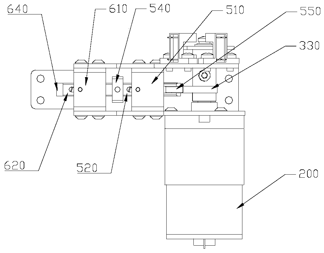
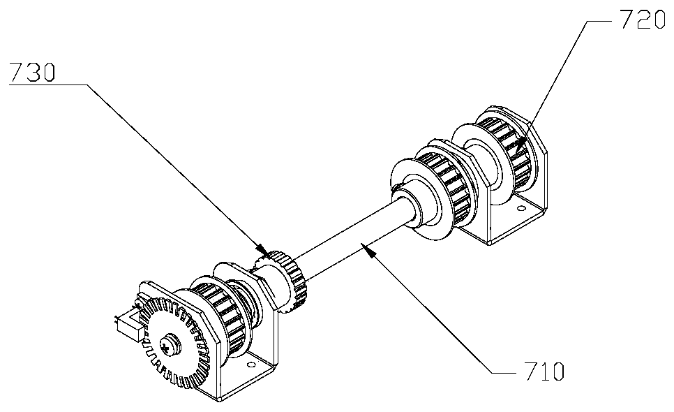
[0043] figure 1 Schematic diagram of the structure of the braking device provided by the embodiment of the present invention at the first viewing angle; figure 2 Schematic diagram of the structure of the braking device provided by the embodiment of the present invention at the first viewing angle; image 3 Schematic diagram of the structure of the synchronous pulley and the brake pulley of the braking mechanism provided by the embodiment of the present invention; Figure 4 A schematic diagram of the opening state of the braking device provided by the embodiment of the present invention; Figure 5 A schematic diagram of the locking state of the braking mechanism provided by the embodiment of the present invention.
[0044] The brake device in this embodiment includes a brake wheel 730, a cam 330, a roller 550, a push rod, a return spring, a locking hook 640, a positioning seat and a driving mechanism.
[0045] Hereinafter, specific structures and positions and connection re...
Embodiment 2
[0058] The braking device of this embodiment is an improvement on the basis of Embodiment 1. The technical content disclosed in Embodiment 1 will not be described repeatedly, and the content disclosed in Embodiment 1 also belongs to the content disclosed in Embodiment 2.
[0059] figure 1 Schematic diagram of the structure of the braking device provided by the embodiment of the present invention at the first viewing angle; figure 2 Schematic diagram of the structure of the braking device provided by the embodiment of the present invention at the first viewing angle; image 3 Schematic diagram of the structure of the synchronous pulley and the brake pulley of the braking mechanism provided by the embodiment of the present invention; Figure 4 A schematic diagram of the opening state of the braking device provided by the embodiment of the present invention; Figure 5 A schematic diagram of the locking state of the braking mechanism provided by the embodiment of the present in...
Embodiment 3
[0065] The braking device of this embodiment is an improvement on the basis of Embodiment 1 and Embodiment 2. The technical content disclosed in Embodiment 1 and Embodiment 2 will not be described repeatedly, and the content disclosed in Embodiment 1 and Embodiment 2 also belongs to this document. The content disclosed in the third embodiment.
[0066] figure 1 The schematic diagram of the structure of the brake device in the first viewing angle provided by the embodiment of the present invention shows the structure and position of the detection mechanism of the brake device.
[0067] In this embodiment, the braking device further includes a detection mechanism, which includes an optical control disc 420 and a photoelectric sensor 410 . The optical control disc 420 is provided with a first opening and a second opening at intervals along its circumferential direction, and the opening size of the first opening is larger than that of the second opening. The photoelectric sensor...
PUM
 Abstract
Description
Claims
Application Information
 - R&D
- Intellectual Property
- Life Sciences
- Materials
- Tech Scout
- Unparalleled Data Quality
- Higher Quality Content
- 60% Fewer Hallucinations
Browse by: Latest US Patents, China's latest patents, Technical Efficacy Thesaurus, Application Domain, Technology Topic, Popular Technical Reports.
© 2025 PatSnap. All rights reserved.Legal|Privacy policy|Modern Slavery Act Transparency Statement|Sitemap|About US| Contact US: help@patsnap.com