
Ship underwater radiation noise assessment method

A radiated noise and ship technology, applied in the field of underwater radiated noise assessment, can solve the problems of inability to demonstrate and evaluate the underwater radiated noise indicators of ships, rough conceptual schemes, and high requirements for known ship parameters, so as to overcome uncertainty and improve Rationality and accuracy, the effect of the method is simple and easy to implement

Active Publication Date: 2019-08-02
HARBIN ENG UNIV
View PDF4 Cites 6 Cited by
  • Summary
  • Abstract
  • Description
  • Claims
  • Application Information

AI Technical Summary

Problems solved by technology

At present, there is no report on the research on the demonstration and evaluation method of underwater radiated noise of ships in the relevant literature or materials at home and abroad.
In the study of ship vibration and noise prediction methods, although there are some mature methods, such as finite element method, boundary element method and statistical energy method, etc., which provide a theoretical basis for the prediction and analysis of ship vibration and noise performance (Wang Xu Zhangming, Wang Yu, Hua Hong magnitude, modeling of ship structure and FEM / BEM calculation of underwater vibration and radiated noise, Ship Mechanics, Vol. In the forecast analysis, it is necessary to obtain parameters such as structural drawings and equipment layout of the analysis pair
However, in the demonstration stage, the concept plan of the ship is relatively rough, with only parameters such as tonnage, overall size and preliminary equipment selection, and it is impossible to carry out the demonstration and evaluation of the ship's underwater radiated noise index according to the existing methods

Method used


Image

  • Ship underwater radiation noise assessment method
  • Ship underwater radiation noise assessment method
  • Ship underwater radiation noise assessment method

Examples


Embodiment Construction

[0034] The following examples describe the present invention in more detail.

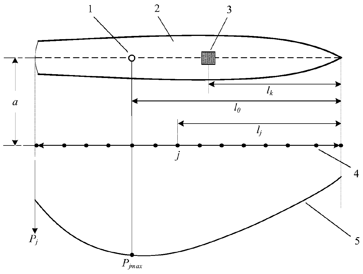
[0035] 1. According to the concept plan of the ship in the demonstration stage, determine the total length of the ship l, the total number of equipment N, and the distance between the kth equipment and the bow l k And its foot vibration acceleration response characteristics X k (ω);

[0036] 2. Calculate the excitation force F at the center of mass of the equipment according to the equipment excitation source load identification formula k (ω)

[0037] f k (ω)=H k (ω) -1 x k (ω)

[0038] In the formula, ω is the frequency, H k (ω) is the vibration acceleration frequency response transfer function matrix from the center of mass of the equipment to the machine foot, which is generally obtained by numerical simulation calculation methods based on finite elements:

[0039] h ki (ω)=x ki (ω)

[0040] In the formula, H ki (ω) is the vibration acceleration frequency response transfer function f...


PUM


Abstract

The invention provides a ship underwater radiation noise assessment method. The method comprises the following steps: 1, inputting ship length, equipment type selection and total number of ship conceptual schemes, and equipment to ship bow distance; 2, identifying the exciting force of the mass center position of the equipment; 3, calculating a far-field underwater radiation noise sound source level and a frequency band sound source level of single-machine equipment of the ship; 4, calculating the total sound level of each point from the bow to the stern at the transverse a-meter position of the ship, drawing a characteristic curve of longitudinal distribution of sound pressure along the ship body as a passing characteristic curve of the ship, and determining the equivalent sound center ofthe ship; 5, estimating an underwater radiation noise source level, a frequency band sound source level and a sound pressure spectrum source level of the ship; and 6, comparing the parameters obtained in the step 5 with a design demand limit value to obtain a ship underwater radiation noise index argumentation and evaluation result. The far-field sound pressure value of the ship under the navigation working condition can be estimated according to the ship concept scheme at the demonstration stage, and demonstration evaluation is carried out on the far-field sound pressure value according to the demand limit value.

Description

technical field [0001] The invention relates to a ship vibration and noise reduction technology, in particular to an underwater radiation noise evaluation method. Background technique [0002] The underwater radiated noise index of ships is mainly used to describe the comprehensive effect of ship vibration and noise reduction measures, and to measure the distance of ships detected by passive sonar. For example, when the total sound level of underwater radiated noise is reduced from 150 decibels to 140 decibels, considering the full-band detection of sonar, the distance of ships detected by passive sonar detection will be shortened to 23% of the original detection distance. [0003] The underwater radiated noise index of a ship is usually evaluated and inspected based on the far-field sound pressure excited by the ship in water. The so-called far field refers to the position at a certain distance from the ship and the ship can be regarded as a point. At present, there is no...

Claims


Application Information

Patent Timeline
IPC IPC(8): G06F17/50
CPCG06F30/15G06F30/20Y02T90/00
Inventor 庞福振霍瑞东王雪仁缪旭弘魏征李海超李玉慧彭德炜
Owner HARBIN ENG UNIV
Learn More