


Quick Research
Generate reliable direction feasibility study reports for your R&D in just a few steps.

Technical Q&A
Discover and master advanced knowledge NOW. Basics, ideas, possibilities, all at once.

Find Solutions
As an expert in R&D theories, this can generate solutions to your technical problems instantly.

Evaluate Feasibility
Analyze your overall solution with one click, know your potential R&D risks in advance.

Monitor Landscape
Get weekly tech updates, stay abreast of the latest tech innovations and key insights.
Combined frame system
A combined frame and frame system technology, applied in the field of combined frame systems, can solve the problems of high cost, poor mechanical properties, and unsightly appearance.
- Summary
- Abstract
- Description
- Claims
- Application Information
AI Technical Summary
Problems solved by technology
Method used
Image

Examples
Embodiment 1
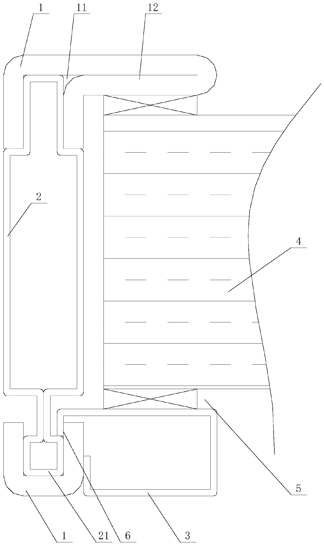
[0034] like figure 1 As shown, the first embodiment of the combined frame system of the present invention includes a plurality of frames, and each frame is enclosed and connected to form a frame system. The middle connecting piece 2 is located between a pair of strong rigidity outer frames 1 and fixedly connects the two strong rigidity outer frames 1. The weak rigidity middle connecting piece 2 or the strong rigidity outer frame 1 is formed with a buckle position 6, and the buckle position 6 is buckled. Equipped with pressure strip 3 or sealing strip 7. The frame system is formed by welding the frame. The frame is composed of a pair of high-rigidity outer frame 1 and weak-rigidity intermediate connecting member 2. The weak-rigidity intermediate connecting member 2 is an intermediate member, which limits a pair of strong rigidity when connected. The effect of the spacing between the rigidity exoskeletons 1. The high-rigidity outer frame 1 is made of thick heavy-duty steel, an...
Embodiment 2
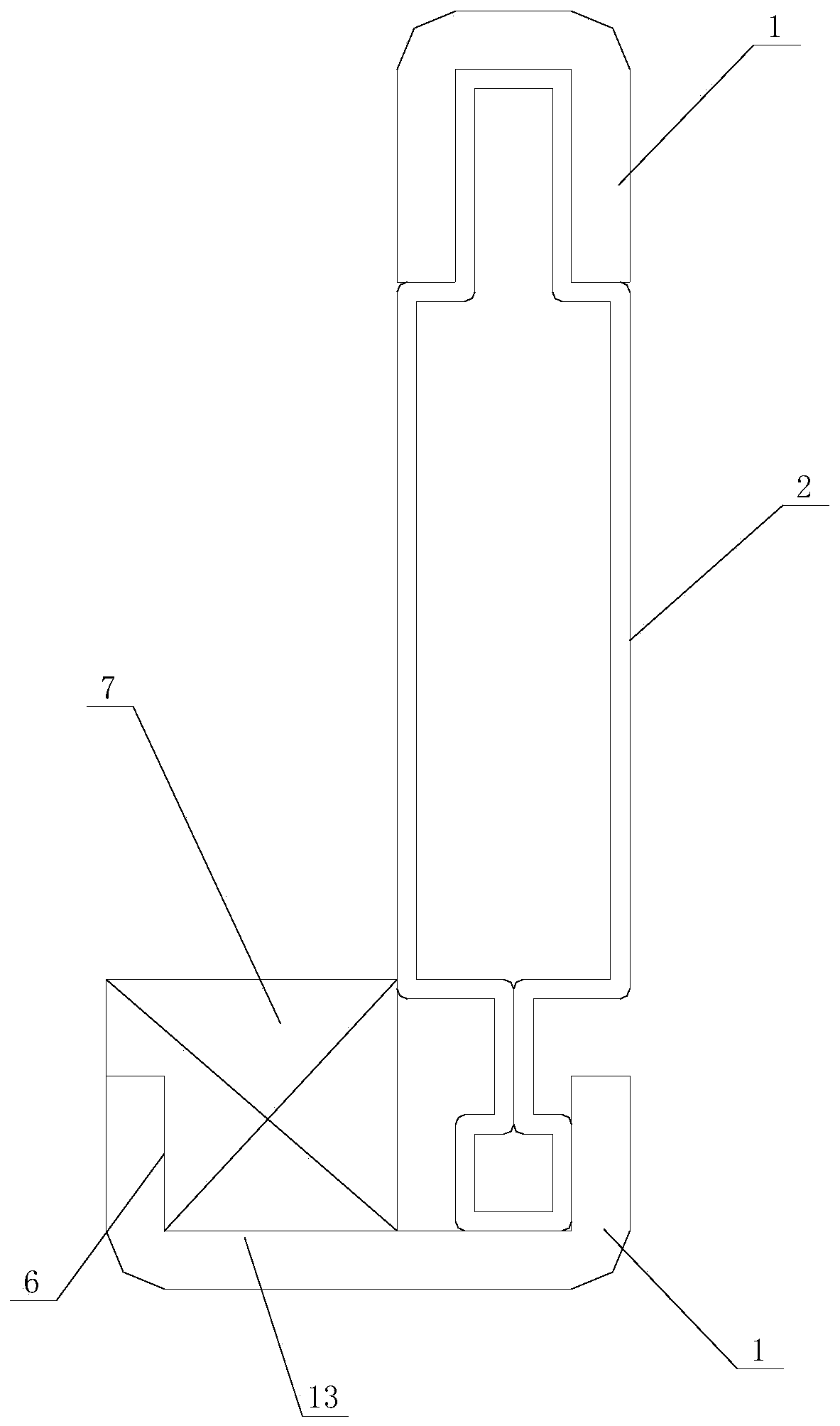
[0040] like figure 2 As shown, the second embodiment of the combined frame system of the present invention is basically the same as the first embodiment, the only difference is that in this embodiment, the buckle position 6 is formed on one side of the high-rigidity outer frame 1, The sealing rubber strip 7 is fastened at the fastening position 6 . In this structure, the sealing rubber strip 7 is buckled with the buckle position 6 to form a sealing edge.
[0041] In this embodiment, one side of one of the strong rigidity outer frame 1 is formed with a limiting portion 13 for contacting with the movable frame system. In this structure, the high-rigidity outer frame 1 only forms the limiting portion 13 for contacting with the movable frame system, and this type of frame is suitable for the fixed frame (without clamping the plate 4).
Embodiment 3
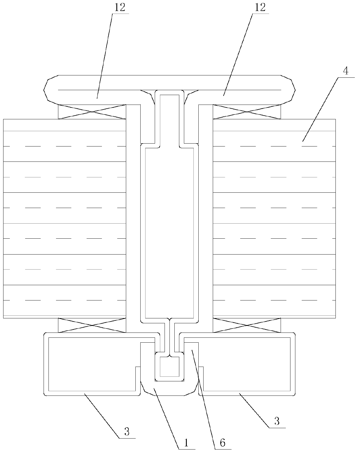
[0043] like image 3 As shown, the third embodiment of the combined frame system of the present invention is basically the same as the first embodiment, with the only difference that: in this embodiment, the snap joints 6 are formed on both sides of the outer frame 1 with high rigidity, The two snap-fit positions 6 are matched to snap and install the two pressure strips 3 . In this structure, the two buckling positions 6 are matched with the buckling strips 3, that is, the two plates 4 are respectively pressed on both sides, which is suitable for the middle fixed frame of the whole system.
PUM
 Abstract
Description
Claims
Application Information
 - R&D Engineer
- R&D Manager
- IP Professional
- Industry Leading Data Capabilities
- Powerful AI technology
- Patent DNA Extraction
Browse by: Latest US Patents, China's latest patents, Technical Efficacy Thesaurus, Application Domain, Technology Topic, Popular Technical Reports.
© 2024 PatSnap. All rights reserved.Legal|Privacy policy|Modern Slavery Act Transparency Statement|Sitemap|About US| Contact US: help@patsnap.com