
Wireless charging and electromagnetic coupling structure and design method thereof

A technology of wireless charging and coupling structure, applied in charging stations, battery circuit devices, electric vehicle charging technology, etc., can solve the problems of high efficiency and limitations, and achieve the goal of improving charging efficiency, reducing magnetic loss, and reducing volume and weight Effect

Pending Publication Date: 2019-08-02
ANHUI UNIVERSITY OF TECHNOLOGY AND SCIENCE
View PDF7 Cites 10 Cited by
  • Summary
  • Abstract
  • Description
  • Claims
  • Application Information

AI Technical Summary

Problems solved by technology

Although the magnetic coupling resonant wireless charging technology has many advantages, it still has limitations compared with the high efficiency of wired charging. The problem now is how to improve the charging efficiency of the magnetic coupling structure of electric vehicle wireless charging

Method used


Image

  • Wireless charging and electromagnetic coupling structure and design method thereof
  • Wireless charging and electromagnetic coupling structure and design method thereof
  • Wireless charging and electromagnetic coupling structure and design method thereof

Examples


Embodiment Construction

[0032] In order to make the object, technical solution and advantages of the present invention clearer, the present invention will be further described in detail below in conjunction with the accompanying drawings and embodiments. It should be understood that the specific embodiments described here are only used to explain the present invention, not to limit the present invention.

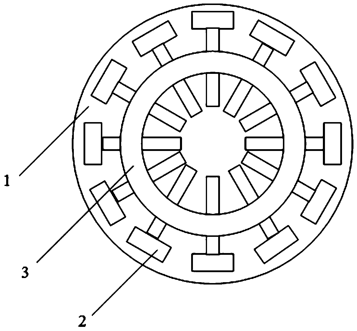
[0033] figure 1 The schematic diagram of the wireless charging magnetic coupling structure provided for the embodiment of the present invention, for the convenience of description, only shows the part related to the embodiment of the present invention.

[0034] The wireless charging coupling structure is suitable for wireless charging of 3.3KW small electric vehicles. The wireless charging coupling structure includes:

[0035] There is an air gap between the transmitting end and the receiving end arranged oppositely, and the receiving end and the transmitting end are arranged coaxially, wherein, t...


PUM


Abstract

The invention is applied to the technical field of wireless charging, and discloses a wireless charging and coupling structure and a design method thereof. The wireless charging and coupling structurecomprises a transmitting end and a receiving end which are arranged oppositely, an air gap is formed between the transmitting end and the receiving end, and the receiving end and the transmitting endare arranged coaxially. The transmitting end sequentially comprises a first aluminum plate, a first magnetic core arranged on the first aluminum plate and a first resonant coil arranged on the firstmagnetic core from outside to inside, wherein the first resonant coil is arranged concentrically with the first magnetic core; the receiving end sequentially comprises a second aluminum plate, a second magnetic core arranged on the second aluminum plate and a second resonance coil arranged on the second magnetic core from outside to inside, wherein the second resonance coil is arranged concentrically with the second magnetic core; and the radius of the first magnetic core is larger than the radius of the second magnetic core, and the radius of the second resonance coil is larger than the radius of the second resonance coil. According to the resonant type electric automobile wireless charging and electromagnetic coupling structure, the coupling degree is improved, the magnetic leakage is reduced, the magnetic loss is reduced, the charging efficiency is improved, the volume and the weight of the magnetic cores are reduced, and the anti-migration capability of the system is improved.

Description

technical field [0001] The invention belongs to the technical field of wireless charging, and provides a wireless charging electromagnetic coupling structure and a design method thereof. Background technique [0002] At present, electric vehicles are mainly charged by wires. Electric vehicles are charged through charging piles. The wired charging method has the following disadvantages: 1. The output power is generally relatively large, resulting in a large current in the charging line. There are great potential safety hazards; 2. The use of plug-in charging method limits the flexibility of electric vehicle charging, and the electrical connection may cause problems such as electric sparks or poor contact during operation, which not only affects the safety of operators, but also greatly reduces 3. In special weather, short circuit and open circuit may occur; 5. Charging piles need to be maintained outdoors for a long time, which increases the charging cost. Wireless charging ...

Claims


Application Information

Patent Timeline
Patent Type & Authority Applications(China)
IPC IPC(8): B60L53/12H02J50/12
CPCH02J7/025B60L53/12H02J50/12Y02T10/70Y02T90/14Y02T10/7072
Inventor 陈其工季乐乐郭欣欣高文根杨运峰余子华胡明星
Owner ANHUI UNIVERSITY OF TECHNOLOGY AND SCIENCE
Learn More