
High-voltage flexible direct-current device capable of reducing capacitor size

A flexible DC and capacitor technology, applied in the direction of output power conversion device, AC power input conversion to DC power output, electrical components, etc., can solve the problem of increasing the current stress of power devices, increasing the current stress of power devices, and not suitable for high voltage Level application and other issues, to achieve the effect of reducing capacitor voltage ripple, reducing system cost, reducing design and installation costs

Active Publication Date: 2019-07-26
ECONOMIC TECH RES INST OF STATE GRID HENAN ELECTRIC POWER +2
View PDF2 Cites 4 Cited by
  • Summary
  • Abstract
  • Description
  • Claims
  • Application Information

AI Technical Summary

Problems solved by technology

In the application number CN201710150668, a structure for eliminating voltage fundamental frequency pulsation is disclosed, but its pulsating power is transmitted through the upper and lower bridge arms, which reduces the modulation ratio and increases the current stress of the power device; MMC capacitor voltage fluctuation suppression method "Peng Kun, etc.) adopts the high-frequency injection method to convert the low-frequency fluctuation of the capacitor voltage into a higher-frequency fluctuation, thereby reducing the fundamental frequency voltage fluctuation, but increasing the current stress of the power device, and the control is complicated; The literature ("New modular multilevel converter with power channels between upper-and lower arms suitable for MV drivers'" He.L etc.) studies a topology in which the upper and lower arms of the bridge arm perform power exchange through the coupling channel, but the coupling The channel needs to withstand the common DC bus level voltage, which increases the insulation cost and is not suitable for high voltage level applications

Method used


Image

  • High-voltage flexible direct-current device capable of reducing capacitor size
  • High-voltage flexible direct-current device capable of reducing capacitor size
  • High-voltage flexible direct-current device capable of reducing capacitor size

Examples


Embodiment 1

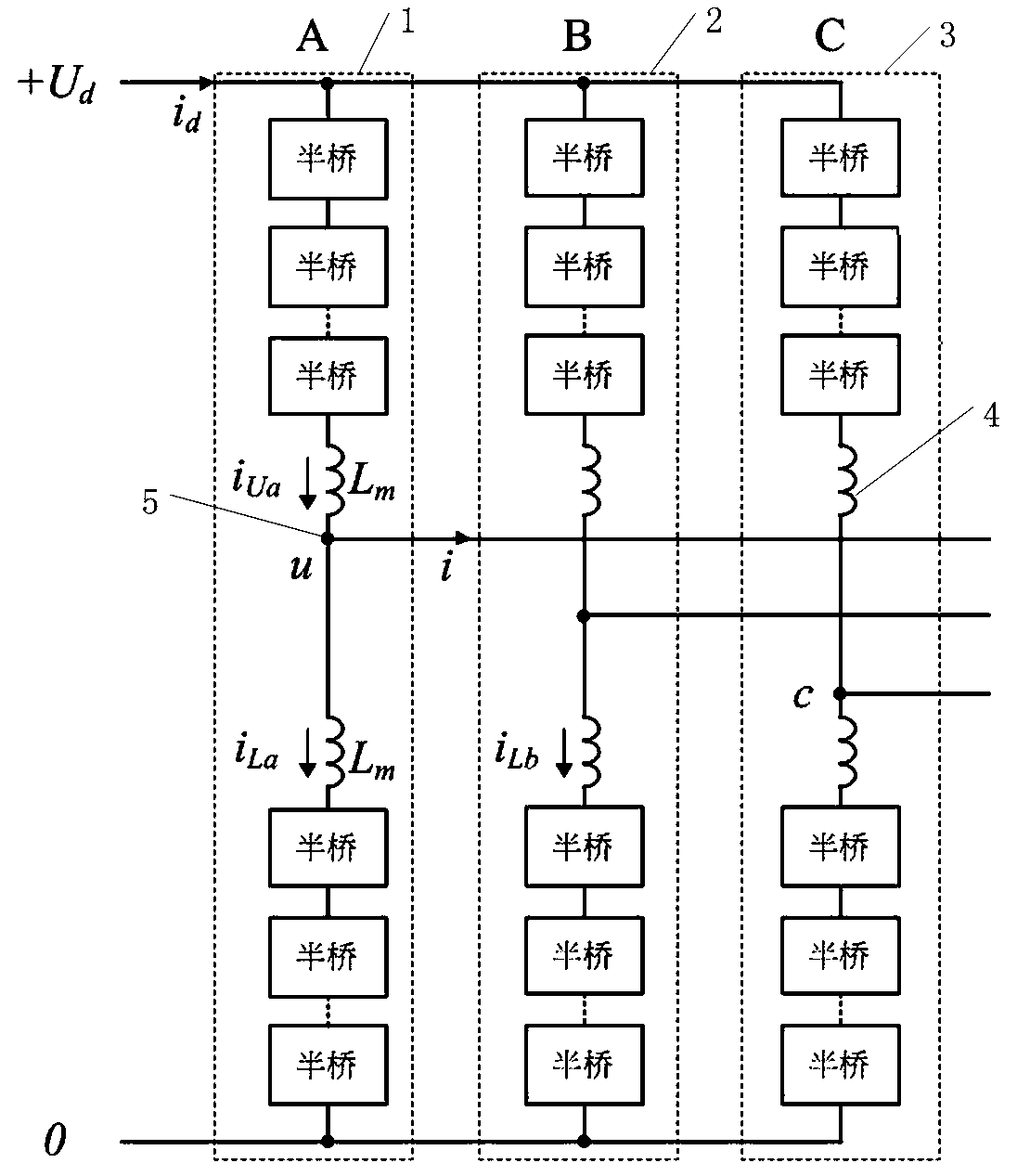
[0033] Such as Figure 2-4 Shown: a high-voltage flexible DC device with reduced capacitance, including three bridge arms A, bridge B, and bridge C with the same structure and connected in parallel. The bridge A is composed of an upper bridge arm and a lower bridge arm in series. The upper bridge arm is composed of a plurality of half-bridge sub-modules connected in series end to end, the structure of the lower bridge arm is the same as that of the upper bridge arm, and two buffer inductors Lm are connected in series between the upper bridge arm and the lower bridge arm. The series connection point between the buffer inductance Lm is an AC output terminal, and the two parallel circuits of the bridge arm A, bridge arm B and bridge arm C are a DC output terminal;

[0034] The AC output end and the DC output end are respectively connected to the DC end and the AC end of the high-voltage flexible DC transmission.

[0035] Both the upper bridge arm and the lower bridge arm are com...


PUM


Abstract

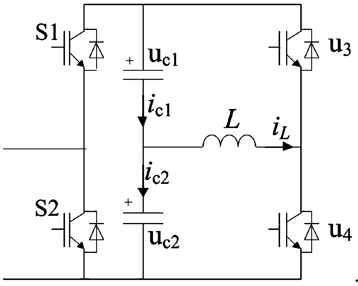
The invention provides a high-voltage flexible direct-current device capable of reducing the capacitor size. The high-voltage flexible direct-current device comprises three bridge arms A, B and C which are the same in structure and are connected in parallel; the bridge arm A is formed by connecting an upper bridge arm and a lower bridge arm in series; the upper bridge arm is formed by connecting aplurality of half-bridge sub-modules end to end in sequence; the lower bridge arm and the upper bridge arm are the same in structure; two buffer inductors Lm are connected between the upper bridge arm and the lower bridge arm in series; a series connection point between the two buffer inductors Lm is an alternating-current output end; and two of the bridge arms A, B and C are connected in parallel to form a direct-current output end. One bridge arm and one energy storage inductor are additionally arranged on one half-bridge sub-module of the device, and the pulse power of a fundamental frequency is transferred to the energy storage inductor, so that the capacitor voltage pulsation is effectively reduced; and due to the modular design, the design and installation cost is reduced, the capacitance value is reduced, the capacitor size is greatly reduced, the size of the system device is directly reduced, and the efficiency of the device is improved.

Description

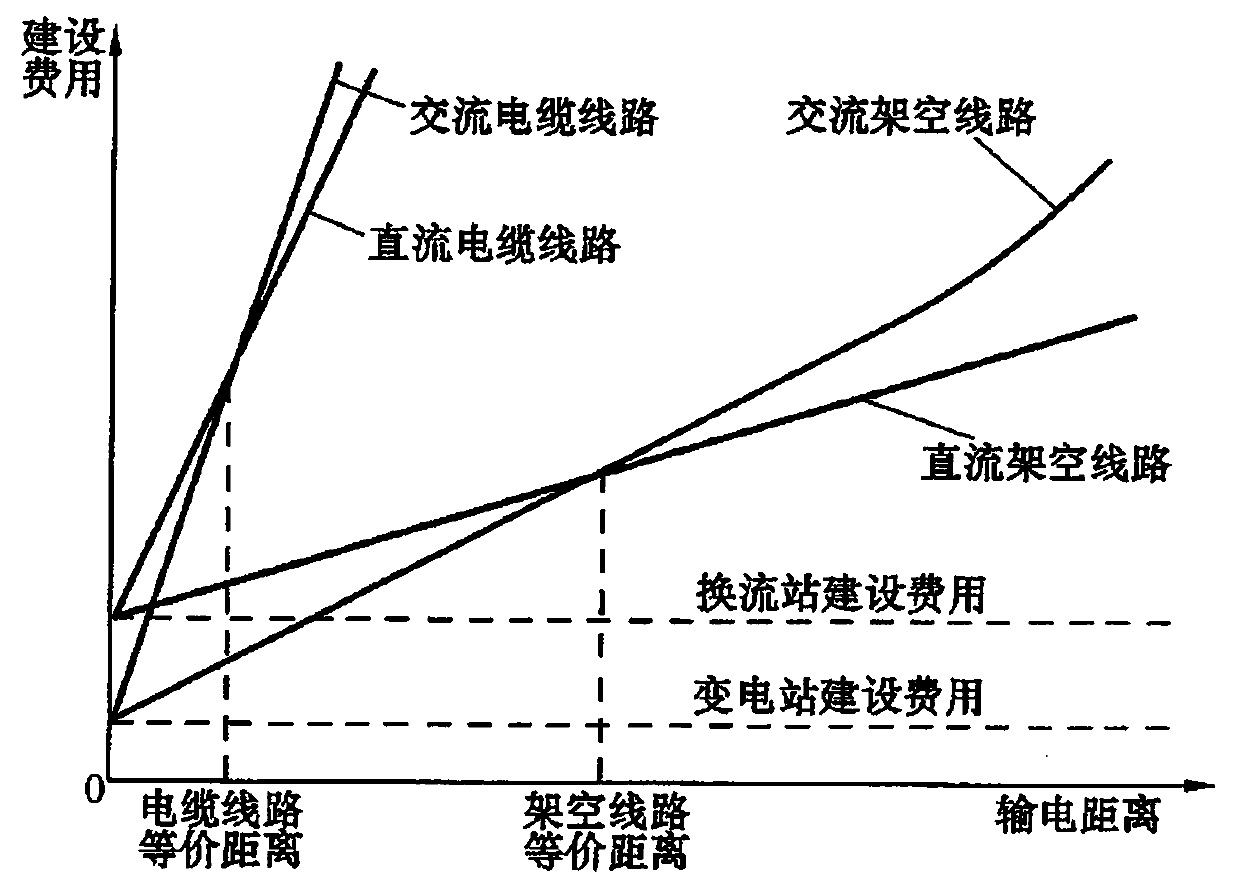
technical field [0001] The invention relates to the technical field of high-voltage flexible direct current transmission, in particular to a high-voltage flexible direct current device with reduced capacitance. Background technique [0002] China has a vast territory and uneven distribution of energy resources: renewable energy sources suitable for large-scale development (such as wind energy, solar energy, and hydropower) are mostly concentrated in the southwest and northeast, and water resources are mainly concentrated in the south-central and northwest regions, accounting for about 15.5% of the national total, 67.8% of the country's total in the southwest region, while the northeast and north China are relatively small, accounting for only about 6% of the country; wind power resources are mainly distributed in northern Xinjiang, Inner Mongolia, northern Gansu, Heilongjiang, eastern Jilin, and Hebei The northern part and the Liaodong Peninsula are suitable for large-scale ...

Claims


Application Information

Patent Timeline
Patent Type & Authority Applications(China)
IPC IPC(8): H02M7/483H02M7/5387
CPCH02M7/483H02M7/5387
Inventor 刘万勋田春筝张凯黄鑫邵红博孙思培张丽华贾鹏
Owner ECONOMIC TECH RES INST OF STATE GRID HENAN ELECTRIC POWER
Learn More