
Transparent border touch screen and preparation method thereof

A touch screen, transparent technology, applied in the direction of equipment with touch panel/sensor/detector, branch office equipment, telephone structure, etc., can solve the problem of high cost of materials, inability of wiring to enter the touch screen, touch screen Problems such as screen-to-body ratio cannot be realized, and achieve the effect of reducing process steps, reducing manufacturing costs, and increasing screen-to-body ratio

Pending Publication Date: 2019-07-26
EELY ECW TECH
View PDF0 Cites 3 Cited by
  • Summary
  • Abstract
  • Description
  • Claims
  • Application Information

AI Technical Summary

Problems solved by technology

[0003] At present, most of the touch screen design traces are generally routed through the frame, and the traces are generally made of opaque metal materials (copper, silver glue, silver bromide or molybdenum lithium molybdenum, etc.), resulting in traces Lines cannot enter the window area of ​​the touch screen, which leads to the inability of the touch screen to achieve an ultra-high screen ratio of 90% to 100%. The screen ratio is the ratio of the area of ​​the window area to the area of ​​the entire touch screen.
In addition, in order to avoid affecting the user experience, it is usually necessary to add ink to block the metal traces of the touch screen frame, which may lead to higher material costs

Method used


Image

  • Transparent border touch screen and preparation method thereof
  • Transparent border touch screen and preparation method thereof
  • Transparent border touch screen and preparation method thereof

Examples


Embodiment 1

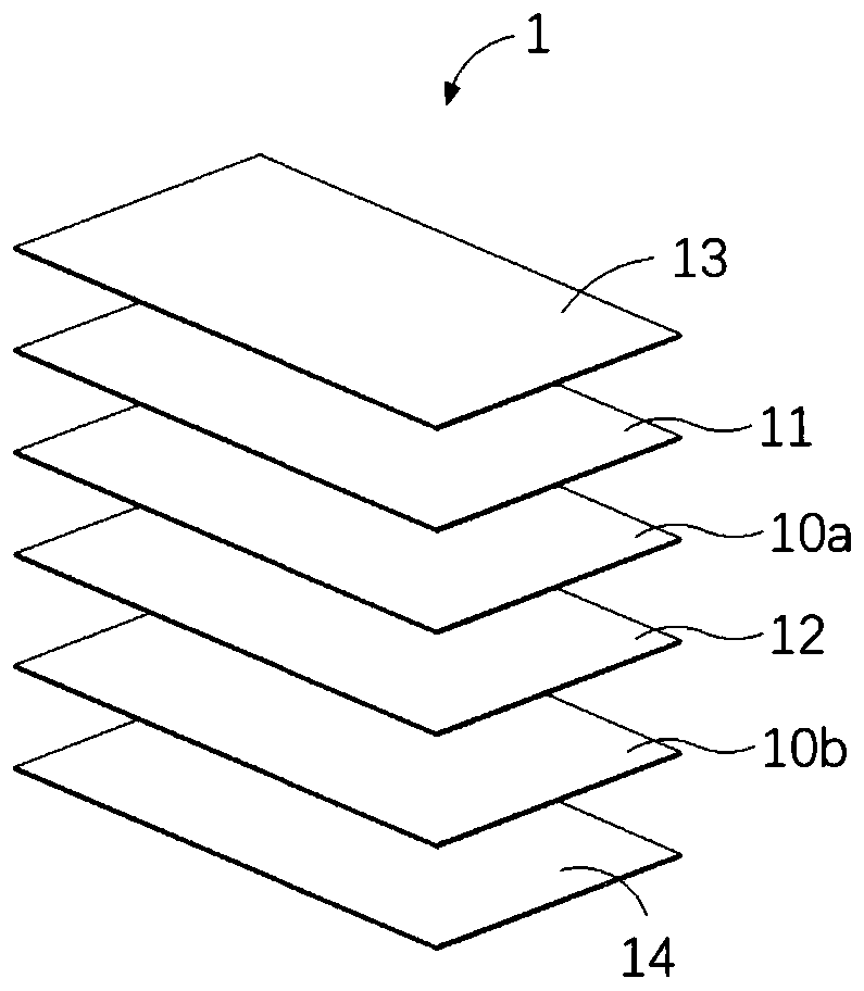
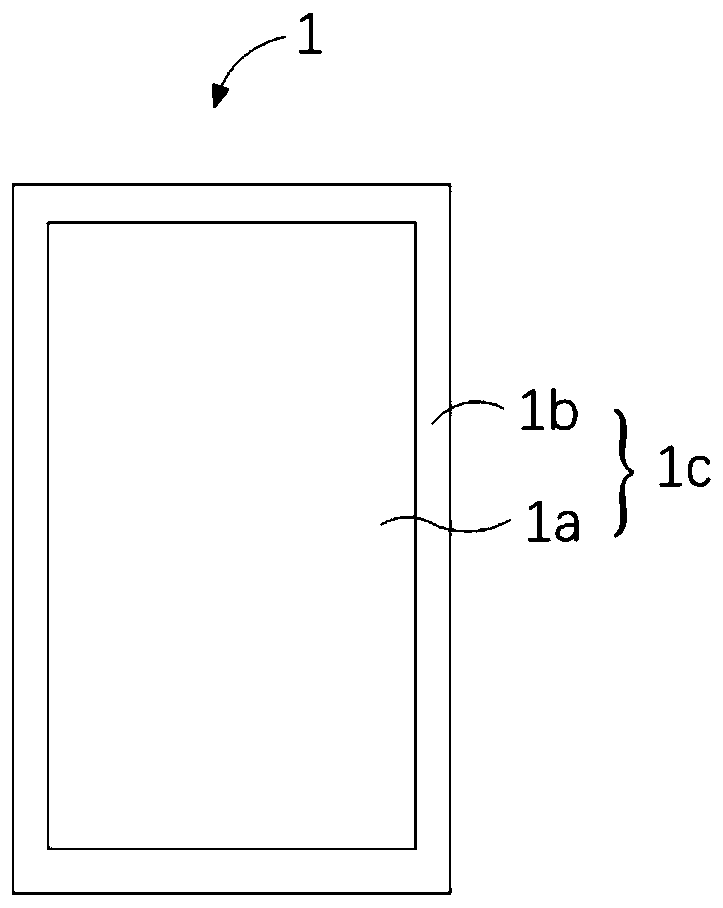
[0071] Please also refer to Figure 1 to Figure 3 , Embodiment 1 of the present invention provides a borderless touch screen, the touch screen 1 includes a polymer film 10, and the polymer film 10 is pasted with a first transparent touch layer 11 and a second transparent touch layer 12 , the second transparent touch layer 12 and the first transparent touch layer 11 are attached to different surfaces of the polymer film 10, and both the first transparent touch layer 11 and the second transparent touch layer 12 include a touch area 1a and The wiring area 1b, the touch area 1a is provided with a touch graphic circuit (not shown), the touch graphic line is provided with a receiving end or a transmitting end, and the wiring area 1b is set around the outer periphery of the touch area 1a, The wiring area 1b is provided with a touch output line (not shown) connected to the receiving end and the transmitting end. The material of the touch output line, the receiving electrode and the em...

Embodiment 2

[0106] Such as Figure 5 and Figure 6 As shown, the present invention provides a method for manufacturing a touch screen based on the first embodiment above, and the method includes the following steps:

[0107] 201. Provide polymer films, cover plates and display screens.

[0108] In this embodiment, the number of layers of the polymer film is preferably one layer, and the material of the polymer film can be polyimides, polyethylene terephthalates, polyacrylics, polyurethanes, rings, etc. Any of olefin polymers and the like.

[0109] 202. Form a first transparent touch layer and a second transparent touch layer on the upper surface and the lower surface of the polymer film respectively, specifically including the following steps:

[0110] 202a. Coating a transparent multi-component alloy on the upper surface and the lower surface of the polymer film to form a first transparent conductive layer and a second transparent conductive layer.

[0111] 202b. Spread a photosensit...

Embodiment 3

[0123] see Figure 7 and see again Figure 5 , Embodiment 3 of the present invention provides a kind of preparation method, the difference between the preparation method of Embodiment 3 of the present invention and the preparation method of Embodiment 2 is:

[0124] 303. Form a first transparent touch layer and a second transparent touch layer on the upper surface and the lower surface of the polymer film respectively, specifically including the following steps:

[0125] 302a, respectively coating a transparent multi-component alloy on the upper surface and the lower surface of the polymer film to form a first transparent conductive layer and a second transparent conductive layer;

[0126] 302b. Perform laser etching on the surfaces of the first transparent conductive layer and the second transparent conductive layer to form the first transparent touch layer and the second transparent touch layer.

[0127] Specifically, the laser etching machine is controlled by computer sof...


PUM

PropertyMeasurementUnit
Square resistanceaaaaaaaaaa

Abstract

The invention discloses a transparent border touch screen and a preparation method thereof. The touch screen comprises a polymer film, the polymer film is provided with a first transparent touch layerand a second transparent touch layer in an attached mode; the second transparent touch layer and the first transparent touch layer are attached to different surfaces of the polymer film; each of thefirst transparent touch layer and the second transparent touch layer comprises a touch area and a wiring area; the touch area is provided with a touch graph circuit; the touch graphic circuit is provided with a receiving end or a transmitting end, the wiring area is annularly arranged on the periphery of the touch area and provided with a touch output circuit connected to the receiving end and thetransmitting end; the touch output circuit, the receiving end and the transmitting end are all made of transparent multi-element alloy, and all or part of the wiring area and the touch area jointly form a window area of the touch screen. According to the transparent border touch screen and the preparation method thereof provided by the embodiment of the invention, the transparent border routing design of the touch screen can be realized, so that all or part of the routing area and the touch area form the window area of the touch screen, and the screen-to-body ratio of the touch screen is improved.

Description

technical field [0001] The invention relates to the technical field of touch film, in particular to a transparent frame touch screen and a preparation method thereof. Background technique [0002] As a simple and convenient way of human-computer interaction, touch screen has been widely used in various fields of our daily life, such as mobile phones, car central control, tablet computers, media players, navigation systems, digital cameras, game equipment, monitors and medical equipment and other fields. [0003] At present, most of the touch screen design traces are generally routed through the frame, and the traces are generally made of opaque metal materials (copper, silver glue, silver bromide or molybdenum lithium molybdenum, etc.), resulting in traces Wires cannot enter the window area of ​​the touch screen, and thus the touch screen cannot achieve an ultra-high screen ratio of 90% to 100%, wherein the screen ratio is the ratio of the area of ​​the window area to the a...

Claims


Application Information

Patent Timeline
IPC IPC(8): G06F3/044H04M1/02H04M1/23
CPCG06F3/044H04M1/026H04M1/0266H04M1/23H04M2250/22G06F2203/04103
Inventor 黄宜浪叶丹霞李学才李明麟
Owner EELY ECW TECH
Learn More