
Doppler radar low-speed measurement method

A Doppler radar and radar technology, applied in the field of Doppler radar low-speed speed measurement, can solve the problems such as the inability of the radar to track the Doppler frequency shift signal, the low sensitivity of the low-speed signal, the inability of the Doppler radar, etc., so as to improve the low-speed signal. Sensitivity, improve sensitivity, reduce the effect of low frequency modulation signal interference

Active Publication Date: 2019-07-26
SHAANXI CHANGLING ELECTRONICS TECH
View PDF12 Cites 1 Cited by
  • Summary
  • Abstract
  • Description
  • Claims
  • Application Information

AI Technical Summary

Problems solved by technology

[0006]At present, Doppler radar generally adopts a simple continuous wave system, which has a shortcoming, that is, the leakage of radar signals and the low-frequency modulation signal caused by beam switching can easily cause radar mistracking Signals near zero frequency
In order to prevent this kind of false tracking, a band-pass filter is usually used to suppress the zero-frequency signal and low-frequency modulation signal, but at the same time, it also suppresses the Doppler frequency shift signal when the aircraft is flying at a low speed.
[0007] When the adopted band-pass filter suppresses the zero-frequency and low-frequency signals to a large extent, the Doppler frequency shift signal at low speed will also be suppressed very much Low, the radar cannot track the Doppler frequency shift signal at low speed, that is, the sensitivity of the low-speed signal is low, and the Doppler radar will lose lock when the aircraft is hovering and flying at low speed, resulting in the Doppler radar not being able to perform low-speed measurements

Method used


Image

  • Doppler radar low-speed measurement method
  • Doppler radar low-speed measurement method
  • Doppler radar low-speed measurement method

Examples


Embodiment Construction

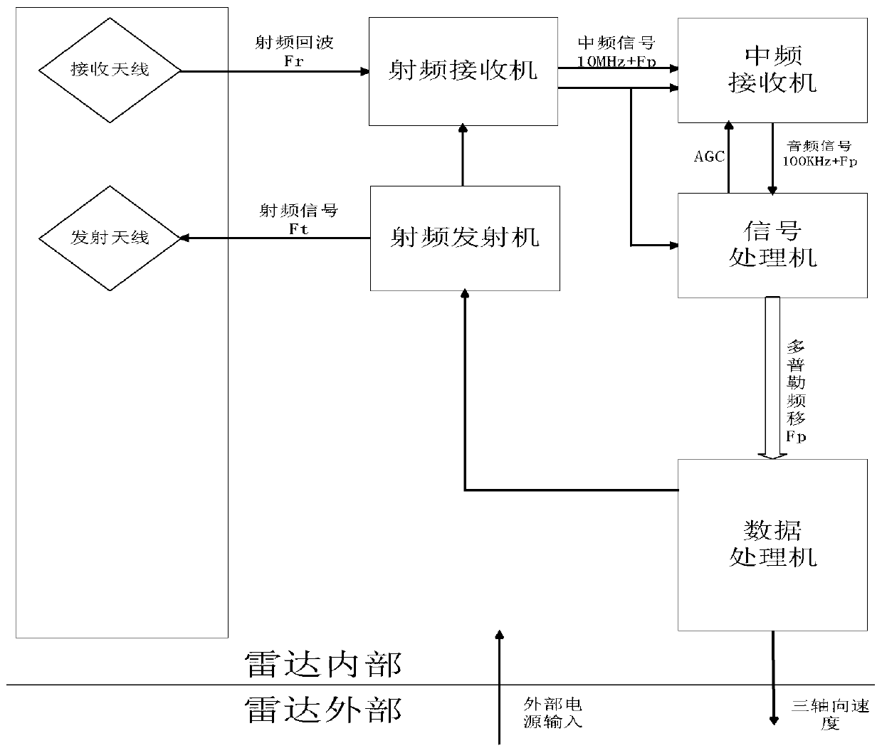
[0033] refer to figure 1 , the working principle of Doppler radar is as follows:

[0034] Doppler radar is mainly composed of power supply, radio frequency transmitter, radio frequency receiver, transmitting antenna, receiving antenna, intermediate frequency receiver, signal processor and data processor.

[0035] The radio frequency transmitter on the Doppler radar generates a radio frequency signal Ft, the radio frequency signal Ft radiates to the reflective surface through the transmitting antenna and then reflects to the space to form a reflected signal Fr. When there is relative motion between the Doppler radar and the reflective surface, the reflected signal Fr Compared with the transmitted signal Ft, the Doppler frequency shift Fp generated by the Doppler effect is increased, and the reflected signal Fr=Ft+Fp at this time. The reflected signal Fr is received by the receiving antenna and enters the radio frequency receiver. After being amplified and mixed in the radio fr...


PUM

PropertyMeasurementUnit
Isolationaaaaaaaaaa
Thicknessaaaaaaaaaa
Absorption rateaaaaaaaaaa

Abstract

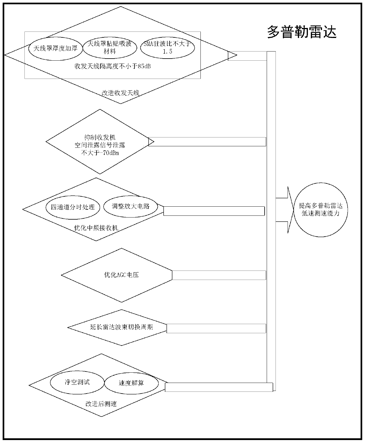
The invention discloses a Doppler radar low-speed measurement method. The Doppler radar low-speed measurement method is mainly used for solving the problem that an existing continuous wave Doppler radar cannot measure the speed when an aerial carrier hovers and flies at the low speed. According to the realization scheme, the Doppler radar low-speed measurement method comprises the steps that 1, anantenna cover of a Doppler radar is thickened, the selected position of the edge of the antenna cover of the Doppler radar is coated with a matched wave-absorbing material, and the standing-wave ratio of a microstrip antenna and radio frequency transceiver cross-linking interface is controlled; 2, the wave-absorbing material is pasted on the upper part of a radio frequency transceiver of the Doppler radar; 3, an amplifying circuit in an intermediate-frequency receiver of the Doppler radar is adjusted, and the intermediate-frequency receiver is optimized; 4, the intermediate-frequency receiveris subjected to AGC control in a mode of combining a PID algorithm and a linear algorithm; 5, the radar wave beam switching period is prolonged; and 6, a low-speed signal of the aerial carrier is measured under the clearance measuring environment through the Doppler radar improved by the steps 1-5. According to the Doppler radar low-speed measurement method, the low-speed measurement ability of the continuous wave Doppler radar is improved, and the Doppler radar low-speed measurement method can be used for stale speed measurement during hovering or low-speed flying of an aircraft.

Description

technical field [0001] The invention belongs to the technical field of radar, and in particular relates to a low-speed speed measurement method of a Doppler radar, which can be used for stable speed measurement when an aircraft is hovering or flying at a low speed. Background technique [0002] Doppler radar uses the Doppler effect to accurately measure the three-axis velocity of the carrier aircraft. The radar transmits and receives electromagnetic waves, and calculates the three-axis relative velocity between the radar carrier and the reflecting surface by calculating the frequency difference between the received electromagnetic wave signal and the transmitted electromagnetic wave signal. [0003] According to the characteristics that the frequency received by the frequency receiver changes with the relative movement between the receiver and the frequency emitter, the difference between the receiving frequency and the transmitting frequency is calculated by the Doppler eff...

Claims


Application Information

Patent Timeline
IPC IPC(8): G01S13/58
CPCG01S13/583Y02A90/10
Inventor 何开巍李栋岂常春利晓芸郝朝亮
Owner SHAANXI CHANGLING ELECTRONICS TECH
Learn More