


Quick Research
Generate reliable direction feasibility study reports for your R&D in just a few steps.

Technical Q&A
Discover and master advanced knowledge NOW. Basics, ideas, possibilities, all at once.

Find Solutions
As an expert in R&D theories, this can generate solutions to your technical problems instantly.

Evaluate Feasibility
Analyze your overall solution with one click, know your potential R&D risks in advance.

Monitor Landscape
Get weekly tech updates, stay abreast of the latest tech innovations and key insights.
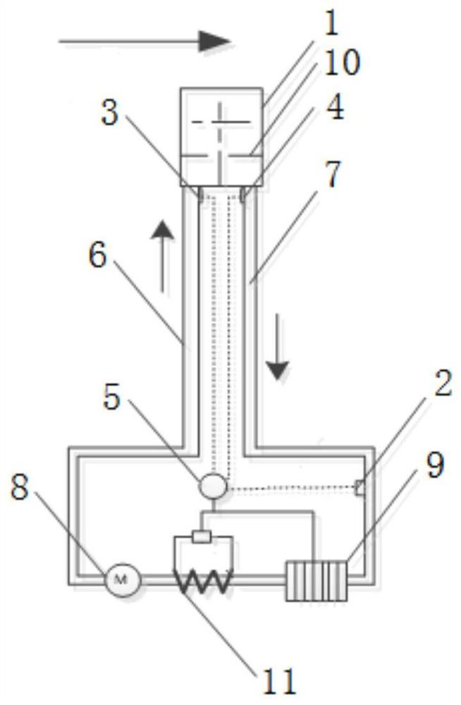
A method and device for measuring fluid velocity based on convective heat transfer
A technology of fluid flow rate and convective heat transfer, which is applied in the direction of measuring fluid velocity by using thermal variables, which can solve the problems of easy breakage of hot wires, influence on the accuracy of measurement results, interference, etc., and achieve accurate measurement results
- Summary
- Abstract
- Description
- Claims
- Application Information
AI Technical Summary
Problems solved by technology
Method used
Image


Examples
Embodiment 1
[0047] When the part where the measuring probe is in contact with the measured fluid is a plate structure, the following heat transfer formula is listed:
[0048]
[0049]
[0050]
[0051]
[0052] Among them: Pr is the Prandtl number, ν is the kinematic viscosity, λ is the thermal conductivity, L is the measuring probe,
[0053] For steady-state heat transfer, due to the critical Reynolds number Re cis a constant, and for a specific fluid, Prandtl number Pr, kinematic viscosity ν and thermal conductivity λ are only related to temperature, so Prandtl number Pr, kinematic viscosity ν and thermal conductivity λ can be calculated according to T k and T w Obtained, the length L of the measuring probe is known, combined with formulas (1), (2), and (3), we can get That is, the fluid flow rate u corresponds to the heat transfer coefficient h one by one, and the formula (4) is brought into the formula Since the heat transfer area A of the measuring probe and the meas...
Embodiment 2
[0055] When the part where the measuring probe is in contact with the measured fluid is a circular tube structure, the following heat transfer formula is listed:
[0056] Nu m =CRe n PR 1 / 3 (1)
[0057]
[0058]
[0059]
[0060] Among them: Pr is the Prandtl number, ν is the kinematic viscosity, λ is the thermal conductivity, L is the measuring probe, C and n are known constants that can be obtained by looking up the table according to the range of Re;
[0061] The fluid velocity u is calculated by formulas (1), (2), (3), and (4).
Embodiment 3
[0063] When the part of the measuring probe in contact with the measured fluid is a spherical structure, the following heat transfer formula is listed:
[0064]
[0065]
[0066]
[0067]
[0068] Among them: Pr is the Prandtl number, ν is the kinematic viscosity, λ is the thermal conductivity, L is the measuring probe, η k For the measured fluid at temperature T k Dynamic viscosity at , η w For the measured fluid at the wall temperature of the measuring probe T w The dynamic viscosity under , and when the measured fluid type and temperature are known, then η k and η w is a known constant.
[0069] The fluid velocity u is calculated by formulas (1), (2), (3), and (4).
[0070] In addition, in step S3, when the heat transfer between the measuring probe and the measured fluid is a steady-state heat transfer, specifically: within a ΔT time, T k The temperature is constant and the input cooling fluid enters the temperature T of the measuring probe 0 constant.
...
PUM
 Abstract
Description
Claims
Application Information
 - R&D Engineer
- R&D Manager
- IP Professional
- Industry Leading Data Capabilities
- Powerful AI technology
- Patent DNA Extraction
Browse by: Latest US Patents, China's latest patents, Technical Efficacy Thesaurus, Application Domain, Technology Topic, Popular Technical Reports.
© 2024 PatSnap. All rights reserved.Legal|Privacy policy|Modern Slavery Act Transparency Statement|Sitemap|About US| Contact US: help@patsnap.com