
Non-negative pressure water supply device and working method thereof

A technology of water supply equipment and non-negative pressure, which is applied in the field of water supply equipment and non-negative pressure water supply equipment. The effect of constant water pressure and water outlet pressure

Inactive Publication Date: 2019-07-26
SHANGHAI WPG WISDOM WATER CO LTD
View PDF5 Cites 3 Cited by
  • Summary
  • Abstract
  • Description
  • Claims
  • Application Information

AI Technical Summary

Problems solved by technology

[0002] Generally, the municipal water pressure cannot be determined, and it is difficult to achieve the best match between the water pressure of the water tank booster pump used for water replenishment and the municipal water pressure.
If the outlet pressure of the water tank water intake pump is set higher than the municipal water supply, the municipal water supply will be limited; if the pressure is low, the municipal water supply will be pressed at the outlet of the water tank water intake booster pump, and water cannot be taken from the water tank
[0003] If the peak duration is short, the booster pump will start instantly and stop the pump instantly, which will bring a lot of energy consumption, and will affect the service life of the pump, and even produce water hammer effect

Method used


Image

  • Non-negative pressure water supply device and working method thereof

Examples


Embodiment Construction

[0029] The present invention will be further described below in conjunction with the accompanying drawings and specific embodiments, but not as a limitation of the present invention.

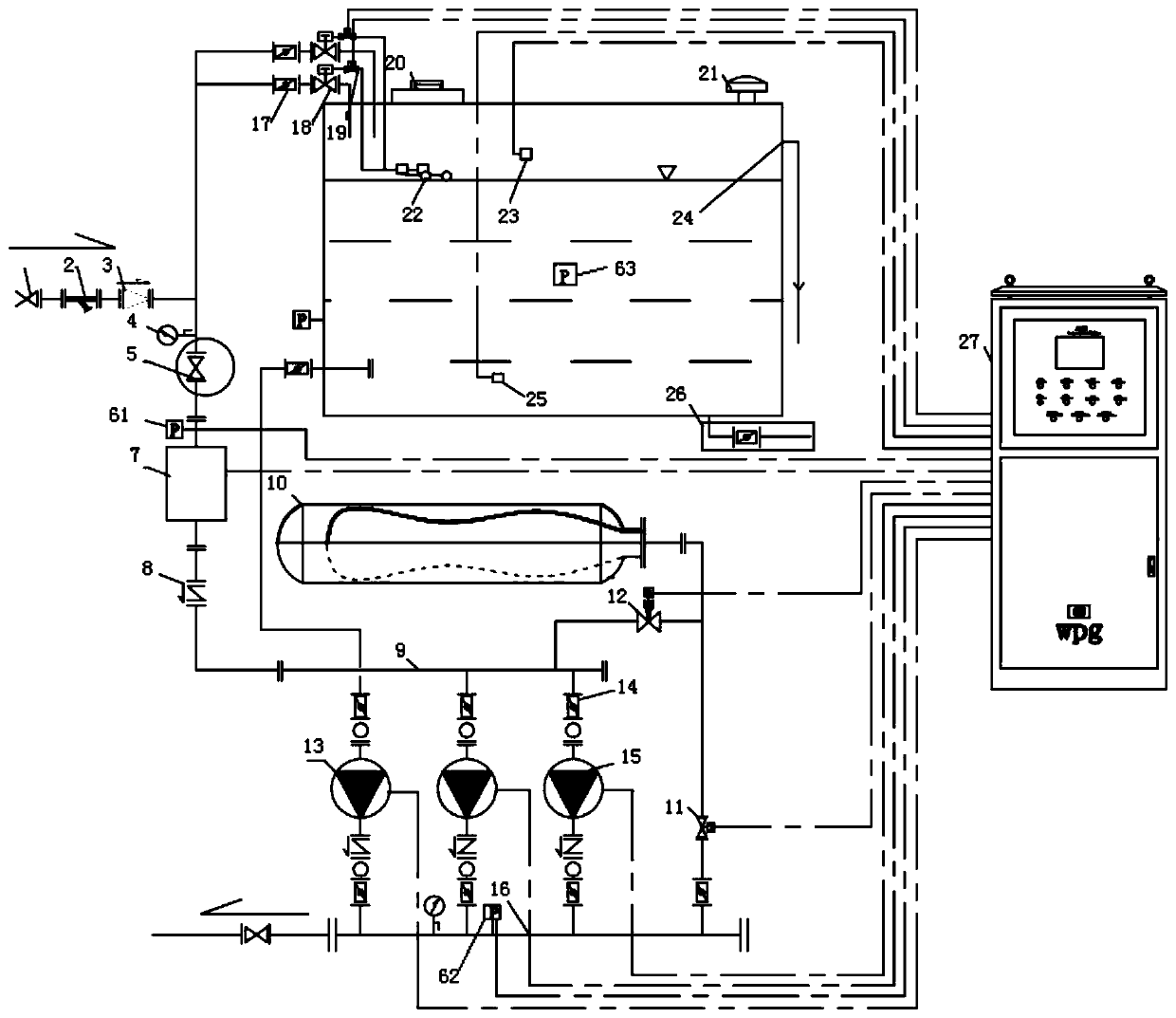
[0030] figure 1 A schematic diagram of a non-negative pressure water supply device of the present invention.

[0031] See figure 1 As shown, a preferred embodiment is shown, a non-negative pressure water supply equipment, including:

[0032] The municipal water channel, the municipal water channel is respectively connected to the water inlet end of the municipal water channel and the water inlet end of the water tank through the valve (1), the Y-shaped filter (2) and the backflow preventer (3); The pressure gauge (4), the valve (5), the first pressure sensor (61), the flow control system (7), and the check valve (8) are connected to the first collecting pipe (9); the water tank is connected to the backflow preventer (3) Two pipelines are arranged between them, and a butterfly valve (17), a va...


PUM


Abstract

The invention discloses a non-negative pressure water supply device. The non-negative pressure water supply device comprises a municipal water inlet channel, a pressure-stabilizing compensation tank,a pressurized pipeline, a main pump assembly and an intelligent control cabinet; the municipal water inlet channel is connected with an inlet end of a municipal water passage and a water inlet end ofa water tank correspondingly, and the municipal water passage communicates with a first summary pipe; the outlet end of the pressure-stabilizing compensation tank communicates with the first summary pipe through an electromagnetic pressure reducing valve, and the outlet end of the pressure-stabilizing compensation tank further communicates with a second summary pipe through an electromagnetic valve; one end of the pressurized pipeline is disposed in the water tank, the other end of the pressurized pipeline communicates with the second summary pipe, and the pressurized pipeline is provided witha water tank water-taking boosting pump; one end of the main pump assembly is disposed in the first summary pipe, and the other end of the main pump assembly is disposed in the second summary pipe; and the intelligent control cabinet controls the entire non-negative pressure water supply device. The non-negative pressure water supply device directly takes water from the water tank and pressurizesthe water to the second summary pipe through the water tank water-taking boosting pump, the service life of the water pump is prevented from being affected, and a water hammer effect is avoided. A third material table and a third waste material table are disposed; and a first robot is located between a second material table and the third material table.

Description

technical field [0001] The invention relates to the technical field of water supply equipment, in particular to the technical field of non-negative pressure water supply equipment. Background technique [0002] Generally, the municipal water pressure cannot be determined, and it is difficult to achieve the best match between the water pressure of the water tank booster pump used for water replenishment and the municipal water pressure. If the outlet pressure of the water intake pump of the water tank is set higher than that of the municipal water, the amount of municipal water will be limited; if the pressure is low, the municipal water will be pressed at the outlet of the water intake booster pump of the water tank, and water cannot be taken from the water tank. [0003] If the peak duration is short, the booster pump will start instantly and stop the pump instantly, which will bring a lot of energy consumption, and will affect the service life of the pump, and even produce...

Claims


Application Information

Patent Timeline
Patent Type & Authority Applications(China)
IPC IPC(8): E03B11/16E03B7/07
CPCE03B7/07E03B11/16Y02A20/00
Inventor 李纪玺李纪伟冯林平
Owner SHANGHAI WPG WISDOM WATER CO LTD
Learn More