Eureka AIR delivers breakthrough ideas for toughest innovation challenges, trusted by R&D personnel around the world.

Microstrip antenna with harmonic suppression function

A microstrip antenna and harmonic suppression technology, applied in the field of antennas, can solve the problem that the microstrip antenna cannot effectively suppress the second and third harmonics, achieve high radiation efficiency and improve radiation efficiency

Active Publication Date: 2019-07-23
CHINA ELECTRONICS TECH GRP NO 26 RES INST
View PDF15 Cites 0 Cited by
  • Summary
  • Abstract
  • Description
  • Claims
  • Application Information

AI Technical Summary

Problems solved by technology

[0005] In view of the above-mentioned deficiencies in the prior art, the purpose of the present invention is to solve the problem that the existing microstrip antenna cannot effectively suppress the second harmonic and the third harmonic, and provide a microstrip antenna with a harmonic suppression function, which can effectively suppress The second and third harmonics, thus greatly improving the radiation efficiency of the microstrip antenna

Method used


Image

  • Microstrip antenna with harmonic suppression function
  • Microstrip antenna with harmonic suppression function
  • Microstrip antenna with harmonic suppression function

Examples


Embodiment

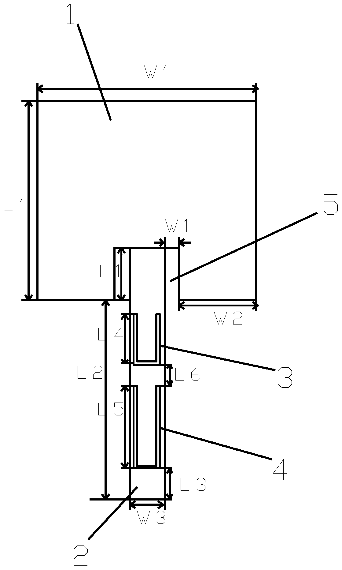
[0024] Example: see figure 1 , a microstrip antenna with harmonic suppression function, including a dielectric substrate and an antenna unit. The antenna unit includes an antenna patch 1 and a microstrip feeder 2. The antenna patch 1 has a rectangular structure and is pasted and fixed on a dielectric substrate. The microstrip feeder 2 is connected to the middle part of one side of the antenna patch 1, and a groove-shaped notch 5 is provided at the positions corresponding to both sides of the microstrip feeder 2 at the connection point between the antenna patch 1 and the microstrip feeder 2; This enables better matching in the working frequency band. In order to improve the stability of the microstrip antenna, the antenna patch 1 and the microstrip feeder 2 are integrally formed.

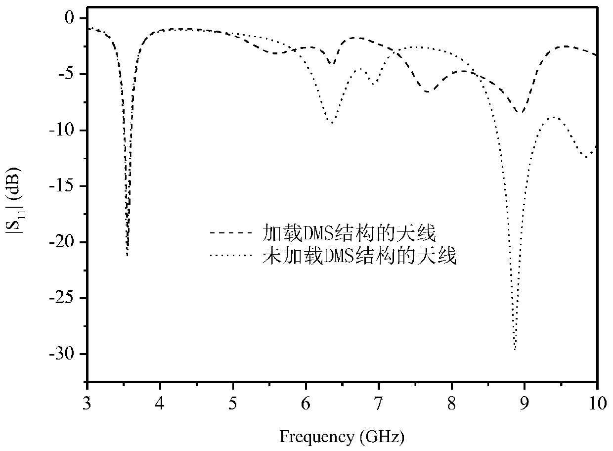
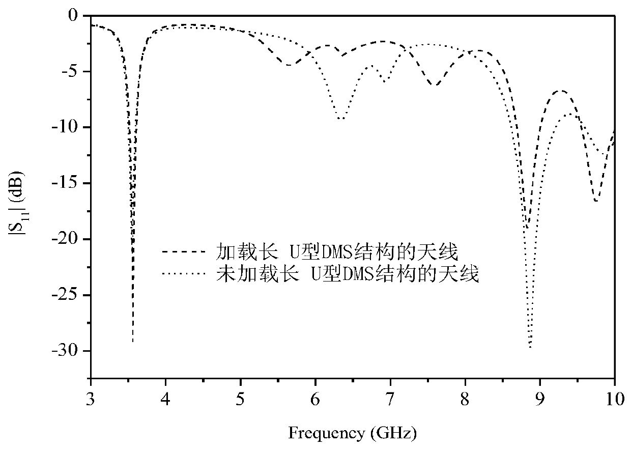
[0025] On the microstrip feeder 2, there are two U-shaped holes distributed along its length direction: the first U-shaped hole 3 and the second U-shaped hole 4, wherein the length of the first U-s...


PUM


Abstract

The invention discloses a microstrip antenna with a harmonic suppression function, which comprises a dielectric substrate and an antenna unit, and the antenna unit comprises an antenna patch and a microstrip feeder line, and the antenna patch is pasted and fixed on the dielectric substrate; the microstrip feeder line is connected with the middle part of one side of the antenna patch, two U-shapedholes, namely a first U-shaped hole and a second U-shaped hole, are distributed in the microstrip feeder line along the length direction of the microstrip feeder line, the length of the first U-shapedhole is smaller than that of the second U-shaped hole, and the opening directions of the two U-shaped holes both face the direction of the antenna patch. According to the invention, second harmonicsand third harmonics can be effectively suppressed, so that the radiation efficiency of the microstrip antenna is greatly improved.

Description

technical field [0001] The invention relates to the technical field of antennas, in particular to a microstrip antenna with a harmonic suppression function. Background technique [0002] An integrated active antenna is a combination of an active device and an antenna. The active antenna can greatly reduce the loss of the antenna feeder, especially when the antenna works at high frequencies, and the active antenna can reduce the power consumption, size and weight. Active antennas are widely used in radar and modern wireless communications. [0003] Since there are active devices inside the active integrated antenna, these active devices will bring harmonic radiation and electromagnetic interference. This harmonic radiation reduces the efficiency of the power amplifier. This problem is solved by embedding a band-stop filter between the passive antenna and the active circuit. Therefore, the harmonic suppression antenna integrates the radiation function of the antenna and th...

Claims


Application Information

Patent Timeline
IPC IPC(8): H01Q1/36H01Q1/38H01Q1/50H01Q13/08
CPCH01Q1/36H01Q1/38H01Q1/50H01Q13/08
Inventor 易礼君余怀强于彦涛
Owner CHINA ELECTRONICS TECH GRP NO 26 RES INST
Why Eureka
Eureka Blog
Learn More