Quasi-constant voltage drop self-stop write-in method of resistive memory unit and circuit thereof
A technology for memory cells and writing circuits, applied in static memory, instruments, etc.
- Summary
- Abstract
- Description
- Claims
- Application Information
AI Technical Summary
Problems solved by technology
Method used
Image
Examples
Embodiment Construction
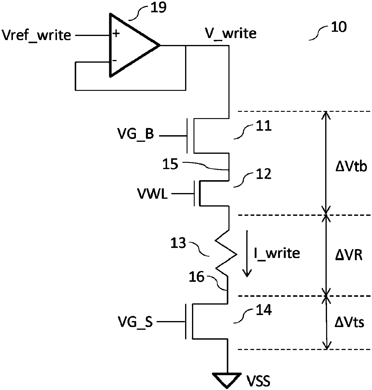
[0101] refer to Figure 1A , which shows a partial circuit schematic diagram of a resistive memory writing circuit in the prior art. The conventional resistive memory write circuit 10 includes: write buffer 19 , transistor 11 , transistor 12 , transistor 14 and resistive memory unit 13 (memory cell). Two ends of the resistive memory unit 13 are respectively connected to the drain of the transistor 14 and the source of the transistor 12 . The source of the transistor 14 is connected to the negative power supply terminal (VSS), and the gate thereof is connected to the voltage VG_S. The drain of transistor 12 is connected to the source of transistor 11 and the gate thereof is connected to voltage VWL. The drain of the transistor 11 is connected to the output terminal of the write buffer 19 and its gate is connected to the voltage VG_B. The connection between the resistive memory unit 13 and the transistor 14 is a local source line 16 (local source line). The connection between...
PUM
 Abstract
Description
Claims
Application Information
 - R&D Engineer
- R&D Manager
- IP Professional
- Industry Leading Data Capabilities
- Powerful AI technology
- Patent DNA Extraction
Browse by: Latest US Patents, China's latest patents, Technical Efficacy Thesaurus, Application Domain, Technology Topic, Popular Technical Reports.
© 2024 PatSnap. All rights reserved.Legal|Privacy policy|Modern Slavery Act Transparency Statement|Sitemap|About US| Contact US: help@patsnap.com


