
A Thin Plate Air-Coupled Ultrasonic Lamb Wave Omnifocus Imaging Detection Method

An air-coupled, focused imaging technology, applied in the analysis of solids using sonic/ultrasonic/infrasonic waves, material analysis using sonic/ultrasonic/infrasonic waves, measurement devices, etc. It can solve the Lamb wave echo signal resolution and signal-to-noise ratio. Low problems, to achieve the effect of improving defect detection ability and high detection signal-to-noise ratio

Active Publication Date: 2021-12-24
NANCHANG HANGKONG UNIVERSITY
View PDF2 Cites 0 Cited by
  • Summary
  • Abstract
  • Description
  • Claims
  • Application Information

AI Technical Summary

Problems solved by technology

[0004] The purpose of the present invention is to provide a thin-plate air-coupled ultrasonic Lamb wave omni-focus imaging detection method to solve the problem of low Lamb wave echo signal resolution and signal-to-noise ratio in the existing detection technology. The present invention is based on the omni-focus The basic principle of imaging, improving the traditional total focusing method, making it suitable for imaging detection of thin plate air-coupled ultrasonic Lamb wave

Method used


Image

  • A Thin Plate Air-Coupled Ultrasonic Lamb Wave Omnifocus Imaging Detection Method
  • A Thin Plate Air-Coupled Ultrasonic Lamb Wave Omnifocus Imaging Detection Method
  • A Thin Plate Air-Coupled Ultrasonic Lamb Wave Omnifocus Imaging Detection Method

Examples


Embodiment Construction

[0045] In order to make the object, technical solution and advantages of the present invention clearer, the present invention will be further described in detail below in conjunction with the accompanying drawings and specific embodiments. It should be understood that the specific embodiments described here are only used to explain the present invention, and are not intended to limit the present invention.

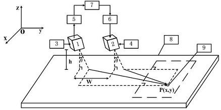
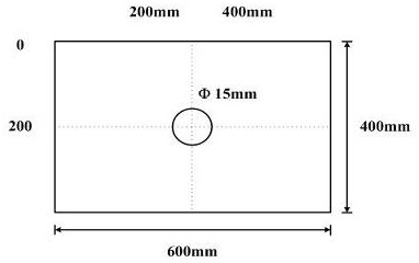
[0046] see Figure 1 to Figure 5 , the present invention works and implements like this, a thin-plate air-coupled ultrasonic Lamb wave full-focus imaging detection device adopts a high-sensitivity non-contact air-coupled ultrasonic signal acquisition system of NAUT, which is composed of JPR600C high-power It is composed of signal transmitter / receiver, probe height, angle adjustment device, preamplifier, signal acquisition card and host device. Its characteristics are: the signal transmitting / receiving probe is arranged on the same side of the thin plate to be tested, the ...


PUM


Abstract

The invention discloses a thin-plate air-coupled ultrasonic Lamb wave all-focus imaging detection method. Different from the traditional ultrasonic array signal acquisition, which is only for a single sound velocity medium, the air-coupled array signal acquisition also needs to consider the propagation time of sound waves in the air. Therefore, the standing wave method and the wave velocity method are used to measure the speed of sound in air c a and the propagation velocity of the Lamb wave in the plate c g . The acquired air-coupled ultrasonic Lamb wave array signal is N ti x N tj x A There is a three-dimensional matrix. The collected air-coupled ultrasonic Lamb wave array signal is divided into imaging grid areas, and the delay time of each scanning path is calculated according to the probe layout position, defect position and sound wave propagation speed. The time-delay rule of the signal realizes the time-delayed superimposition of all-focus imaging. The invention is expected to expand the high-quality ultrasonic full-focus technology to thin-plate air-coupled ultrasonic Lamb wave imaging detection, and effectively improves the defect detection capability.

Description

technical field [0001] The invention relates to the field of ultrasonic non-destructive testing, in particular to a thin-plate air-coupled ultrasonic Lamb wave all-focus imaging detection method. Background technique [0002] As a new type of non-destructive testing technology, non-contact air-coupled ultrasonic testing makes up for the traditional ultrasonic testing due to its characteristics of no coupling agent, no secondary pollution of material components, and the ability to arrange sensors on one side for in-service testing. lack of. Furthermore, due to the characteristics of fast propagation speed, long propagation distance, and sensitivity to defects in laminates, combined with air-coupled ultrasonic testing technology, Lamb waves have become one of the most widely used detection methods for thin-plate components today, and have been recognized in China. Highly recognized by foreign research scholars. However, due to the use of air medium coupling, the acoustic imp...

Claims


Application Information

Patent Timeline
Patent Type & Authority Patents(China)
IPC IPC(8): G01N29/04
CPCG01N29/041G01N2291/023
Inventor 张柏源陈尧纪霖轩冒秋琴马啸啸刘晟刘宏付桂英
Owner NANCHANG HANGKONG UNIVERSITY
Learn More