
Industrial robot visual servo system and servo method and device

An industrial robot and visual servo technology, applied in the field of robotics, can solve the problems of high manpower cost, increased difficulty of visual recognition, prone to omissions and errors, etc., to facilitate operation and management, realize real-time tracking, and improve workflow Effect

Inactive Publication Date: 2019-07-23
北京无远弗届科技有限公司
View PDF6 Cites 23 Cited by
  • Summary
  • Abstract
  • Description
  • Claims
  • Application Information

AI Technical Summary

Problems solved by technology

[0006] However, the existing industrial robot visual servo system for welding automation has the following problems: First, it does not solve the problem of difficult teaching of robots in welding automation production. Teaching reproduction is a method commonly used in the field of robots, that is, through The teaching pendant adapted to the robot manipulates the joint movement of the robot so that the robot moves to a predetermined position, and at the same time records the position and transmits it to the robot controller, and the subsequent robot can automatically repeat the task according to the instruction
Since welding has high requirements on spatial position accuracy and many requirements on welding posture, this work usually takes a long time and the process is cumbersome, prone to omissions and mistakes. high skill requirements
Second, the problem of welding versatility has not been solved. Due to the wide variety of welding workpieces and the different types of weld seams, it is difficult for the current visual recognition effect to reach a usable level on all workpieces.
In addition, errors caused by workpiece reflection and arc light interference also greatly increase the difficulty of visual recognition
Third, there is no integrated closed-loop solution. The aforementioned industrial robot visual servo system for welding automation can only be called a seam tracker in a strict sense. , system calibration, reproduction to a complete set of solutions for welding real-time tracking
Operators often need to learn how to operate a variety of different systems, such as learning how to use the robot teach pendant and the weld seam tracker. At the same time, they also need to learn how to calibrate the vision system and the robot system and other complicated knowledge, which is labor-intensive. the cost is too high

Method used


Image

  • Industrial robot visual servo system and servo method and device
  • Industrial robot visual servo system and servo method and device
  • Industrial robot visual servo system and servo method and device

Examples


Embodiment Construction

[0050] The specific embodiments of the present invention will be further described below in conjunction with the accompanying drawings. The following examples are only used to illustrate the technical solution of the present invention more clearly, but not to limit the protection scope of the present invention.

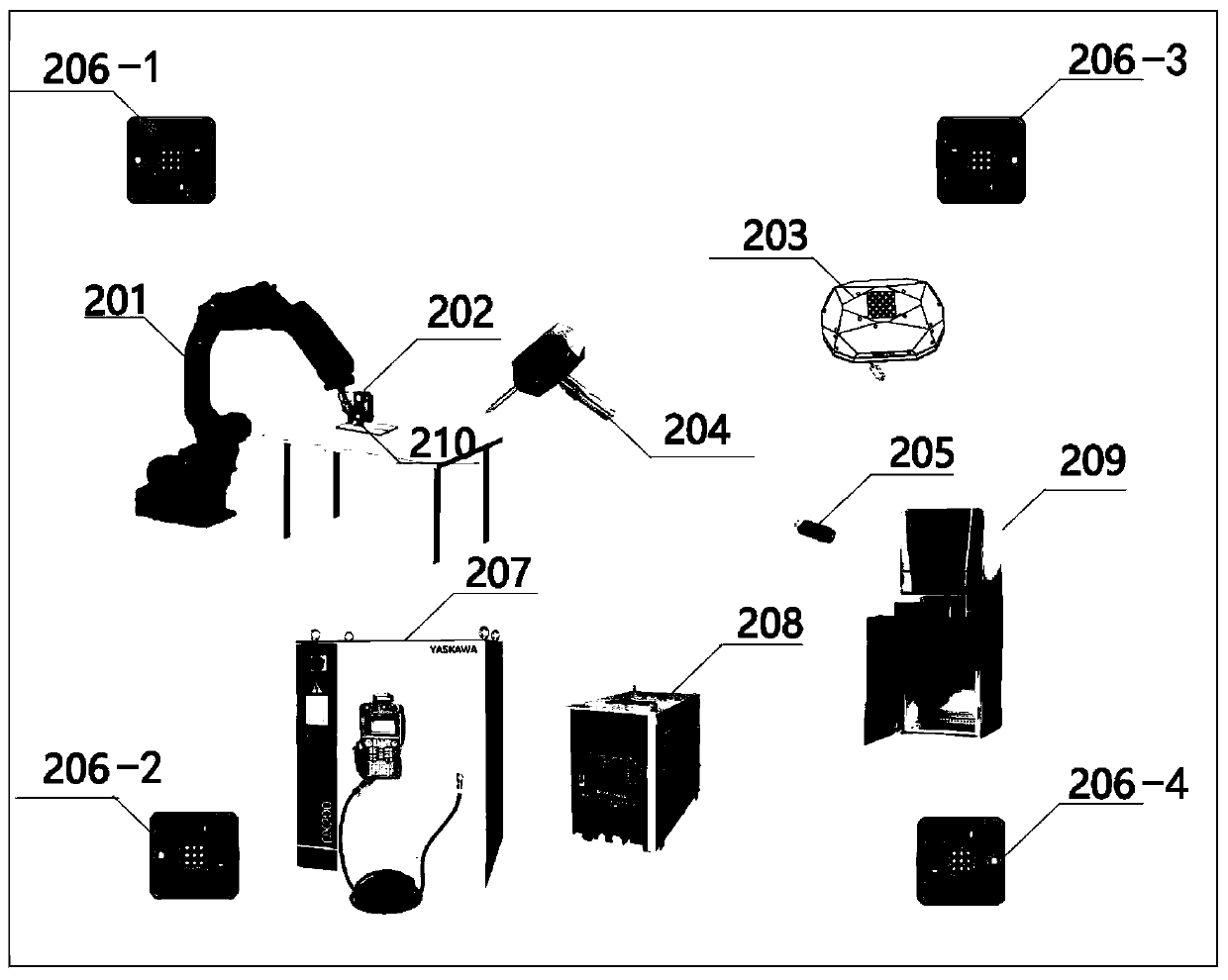
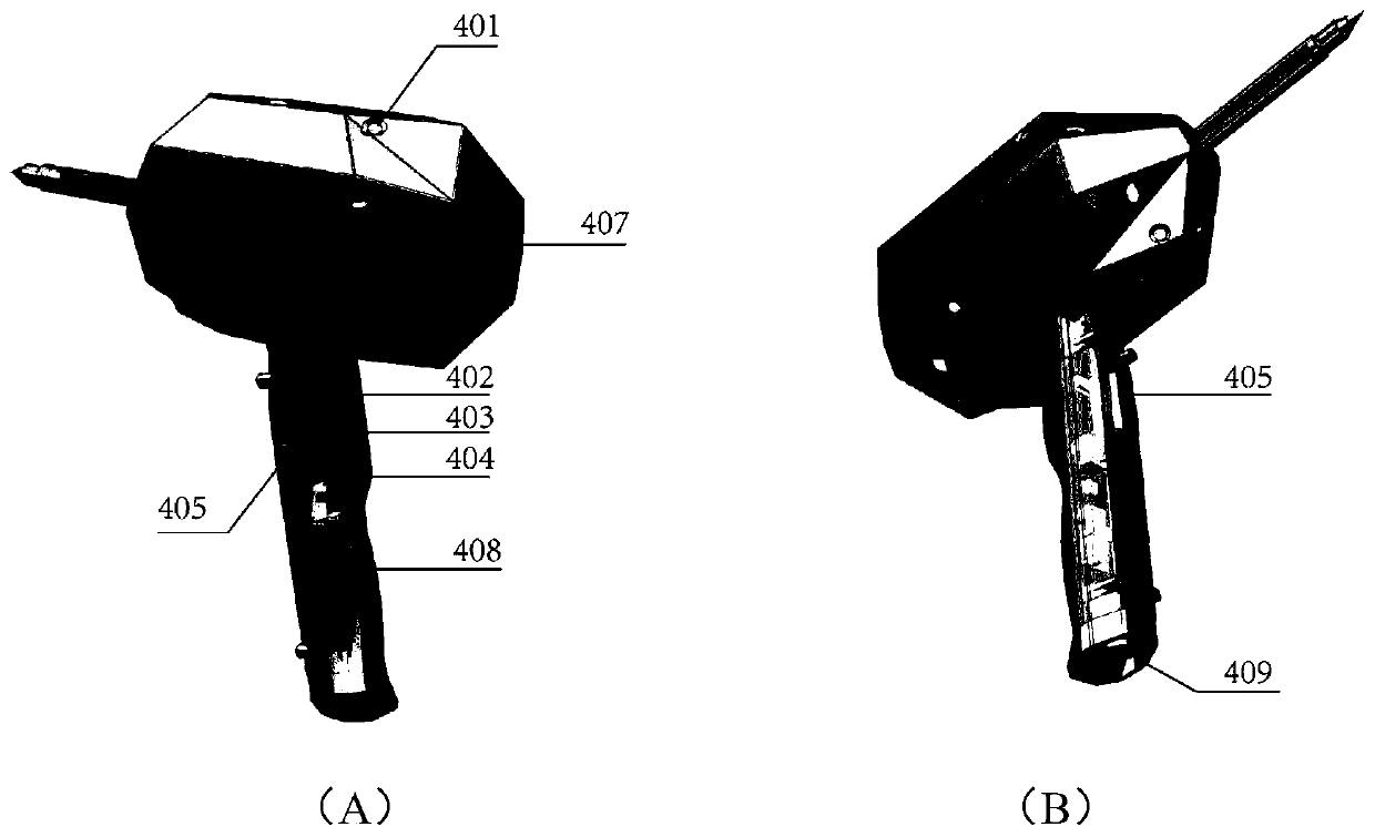
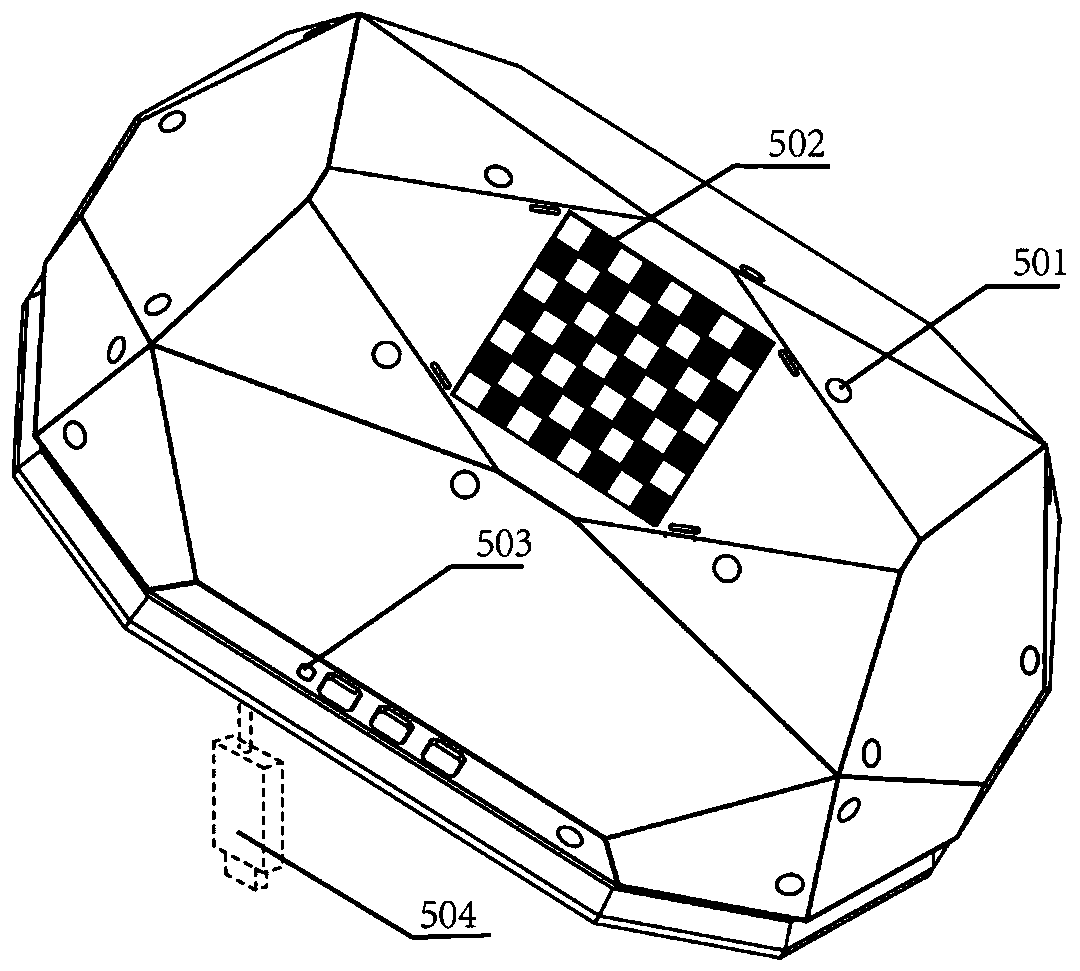
[0051] figure 1 It shows a schematic diagram of the composition of an industrial robot visual servo system provided in this embodiment, including: a six-axis robot 201, a seam tracker 202, a calibration object 203, a wireless handheld teaching device 204, a USB wireless receiver 205, an infrared Laser positioning base station 206, robot control cabinet 207, welding machine power supply control cabinet 208, upper computer control cabinet 209 and automatic wire feeding system.

[0052] The seam tracker 202 is fixed on the first end of the six-axis robot 201 and connected to the upper computer control cabinet 209 through Ethernet.

[0053] The calibration object 203 is...


PUM


Abstract

The embodiment of the invention discloses an industrial robot visual servo system and a servo method and device. The industrial robot visual servo system comprises a six-axis robot, a weld joint tacker, a calibration object, a wireless handheld demonstrator, a USB wireless receiver, an infrared laser positioning base station, a robot control cabinet, a welding machine power supply control cabinet,an upper computer control cabinet and an automatic wire feeding system. Rapid demonstration without programming is achieved, non-uniform workpiece incoming is avoided, and real-time tracking of welding thermal deformation is achieved; the working process of a traditional welding automatic system is improved, and an operator does not need to use the demonstrator to carry out complex demonstrationprogramming; as the recognition technology based on deep learning is adopted for weld joint tracking, the universality of welding automation is greatly improved; and in addition, welding path planning, demonstration, system calibration and welding real-time tracking are completely integrated in the same upper computer interface, and therefore the process operation and management can be conveniently carried out by the operator.

Description

technical field [0001] The invention relates to the technical field of robots, in particular to an industrial robot visual servo system, a servo method and a device. Background technique [0002] The mechanical arm is the most widely used automatic mechanical device in the field of robotics. It is widely used in industrial manufacturing, medical treatment, entertainment services, military, semiconductor manufacturing and other fields. Although the common six-degree-of-freedom mechanical arm pose accuracy Now it can achieve a very high level, but to achieve high precision in actual use requires complex simulation and on-site teaching processes to achieve. At the same time, there are high requirements for the consistency of the workpiece, and it lacks the intelligence to correct deviations independently. [0003] In the 1960s, due to the development of robots and computer technology, people began to study robots with visual functions, aiming to collect and analyze the images o...

Claims


Application Information

Patent Timeline
IPC IPC(8): B25J9/00B25J9/16B23K37/00B23K37/02
CPCB23K37/00B23K37/0252B25J9/0081B25J9/1664
Inventor 郭颜京天刘昊
Owner 北京无远弗届科技有限公司
Learn More