
Polishing machine and polishing technology

A polishing machine and process technology, which is applied in the direction of surface polishing machine tools, grinding/polishing equipment, manufacturing tools, etc., can solve the problems of partial grinding of polishing wheels and affect the polishing quality, so as to avoid partial grinding, high polishing efficiency, and improve Polished quality effects

Pending Publication Date: 2019-07-23
珠海广鑫厨卫科技有限公司
View PDF0 Cites 2 Cited by
  • Summary
  • Abstract
  • Description
  • Claims
  • Application Information

AI Technical Summary

Problems solved by technology

[0004] However, it is difficult for the polishing wheel to evenly fit the inclined side walls of products such as sinks and pots, which leads to serious partial wear of the polishing wheel and affects the polishing quality

Method used


Image

  • Polishing machine and polishing technology
  • Polishing machine and polishing technology
  • Polishing machine and polishing technology

Examples


Embodiment Construction

[0023] This part will describe the specific embodiment of the present invention in detail, and the preferred embodiment of the present invention is shown in the accompanying drawings. Each technical feature and overall technical solution of the invention, but it should not be understood as a limitation on the protection scope of the present invention.

[0024] In the description of the present invention, it should be understood that the orientation descriptions, such as up, down, front, back, left, right, etc. indicated orientations or positional relationships are based on the orientations or positional relationships shown in the drawings, and are only In order to facilitate the description of the present invention and simplify the description, it does not indicate or imply that the device or element referred to must have a specific orientation, be constructed and operated in a specific orientation, and thus should not be construed as limiting the present invention.

[0025] I...


PUM


Abstract

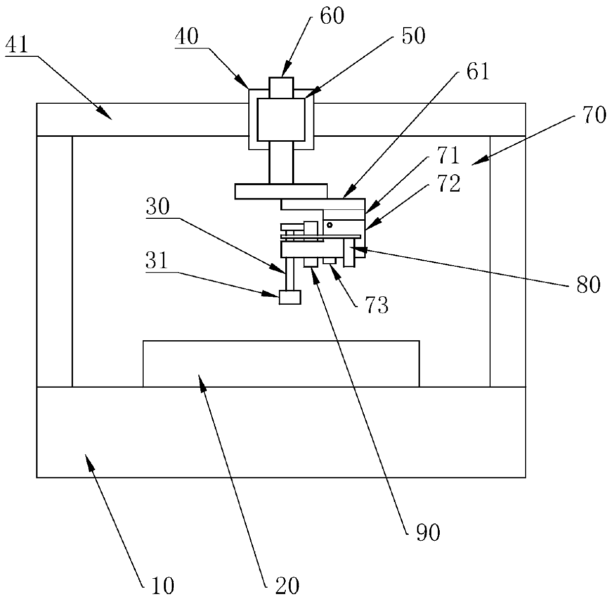
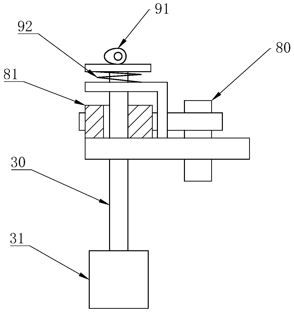
The invention discloses a polishing machine and a polishing technology. The polishing machine comprises a rack. The rack is provided with a clamp and a polishing shaft. The clamp can move in the Y direction. The rack is provided with an X-direction moving assembly. The X-direction moving assembly is provided with a Z-direction moving assembly. The Z-direction moving assembly is provided with a Z-direction rotating assembly. The Z-direction rotating assembly is provided with a horizontal moving assembly. The horizontal moving assembly is provided with a swing assembly. The swing direction of the swing assembly is perpendicular to the horizontal moving direction of the horizontal moving assembly. The swing assembly comprises a first frame body connected with the horizontal moving assembly and a second frame body rotationally connected with the first frame body, the first frame body is provided with a first motor driving the second frame body to swing and adjust, and the second frame bodyis connected with the polishing shaft. The second frame body is provided with a second motor driving the polishing shaft to rotate. The polishing shaft is arranged above the clamp, the axis directionof the polishing shaft is arranged in the up-down direction, and the polishing shaft is sleeved with a polishing wheel. By means of the polishing machine and the polishing technology, eccentric wearof the polishing wheel can be reduced, and the polishing quality is ensured.

Description

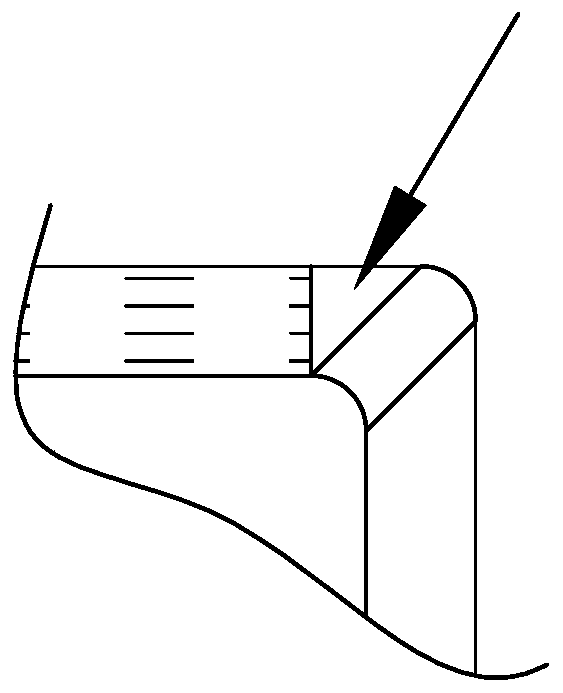
technical field [0001] The invention relates to polishing equipment, in particular to a polishing machine and a polishing process. Background technique [0002] In the prior art, products such as sinks and pots need to be surface polished after stamping to meet the appearance quality requirements. [0003] A common polishing machine includes a rotating shaft driven by a motor, and a polishing wheel is set on the rotating shaft. Driven by the motor, the rotating shaft rotates at high speed, and then the rotating shaft drives the polishing wheel to rotate at high speed, so that the product surface contacts the radially outer surface of the polishing wheel, and the polishing wheel polishes the product surface. [0004] However, it is difficult for the polishing wheel to fit evenly on the inclined side walls of products such as sinks and pans, which leads to severe partial wear of the polishing wheel and affects the polishing quality. Contents of the invention [0005] The p...

Claims


Application Information

Patent Timeline
Patent Type & Authority Applications(China)
IPC IPC(8): B24B29/00B24B41/06B24B47/20
CPCB24B29/00B24B41/06B24B47/20
Inventor 肖宇飞
Owner 珠海广鑫厨卫科技有限公司
Learn More