An opposed burner system for a supercritical carbon dioxide coal-fired boiler

A carbon dioxide, coal-fired boiler technology, which is applied in the combustion of various fuels, the combustion of lump fuel and powder fuel, the combustion of lump fuel and gaseous fuel, etc. Large temperature deviation, unstable flame and other problems, to achieve the effect of efficient and stable pulverized coal combustion, preventing local over-temperature, and eliminating potential safety hazards

Active Publication Date: 2020-04-03
HUAZHONG UNIV OF SCI & TECH
View PDF4 Cites 0 Cited by
  • Summary
  • Abstract
  • Description
  • Claims
  • Application Information

AI Technical Summary

Problems solved by technology

However, no matter increasing the size of the boiler or increasing the inner wall surface, there will be problems of unstable flame and large deviation of outlet smoke temperature during combustion of pulverized coal.
Due to the characteristics of the supercritical carbon dioxide Brayton cycle, the temperature and pressure of the carbon dioxide working medium at the boiler inlet are very high, and the heat transfer coefficient is small at the same time. The combination of these two problems will lead to a particularly high wall temperature in the peak heat load area of ​​the boiler, and there is an explosion. pipe safety hazards
Therefore, there is a lack of effective means to apply supercritical carbon dioxide in the hedging burner system in the prior art

Method used


Image

  • An opposed burner system for a supercritical carbon dioxide coal-fired boiler
  • An opposed burner system for a supercritical carbon dioxide coal-fired boiler

Examples


Embodiment 1

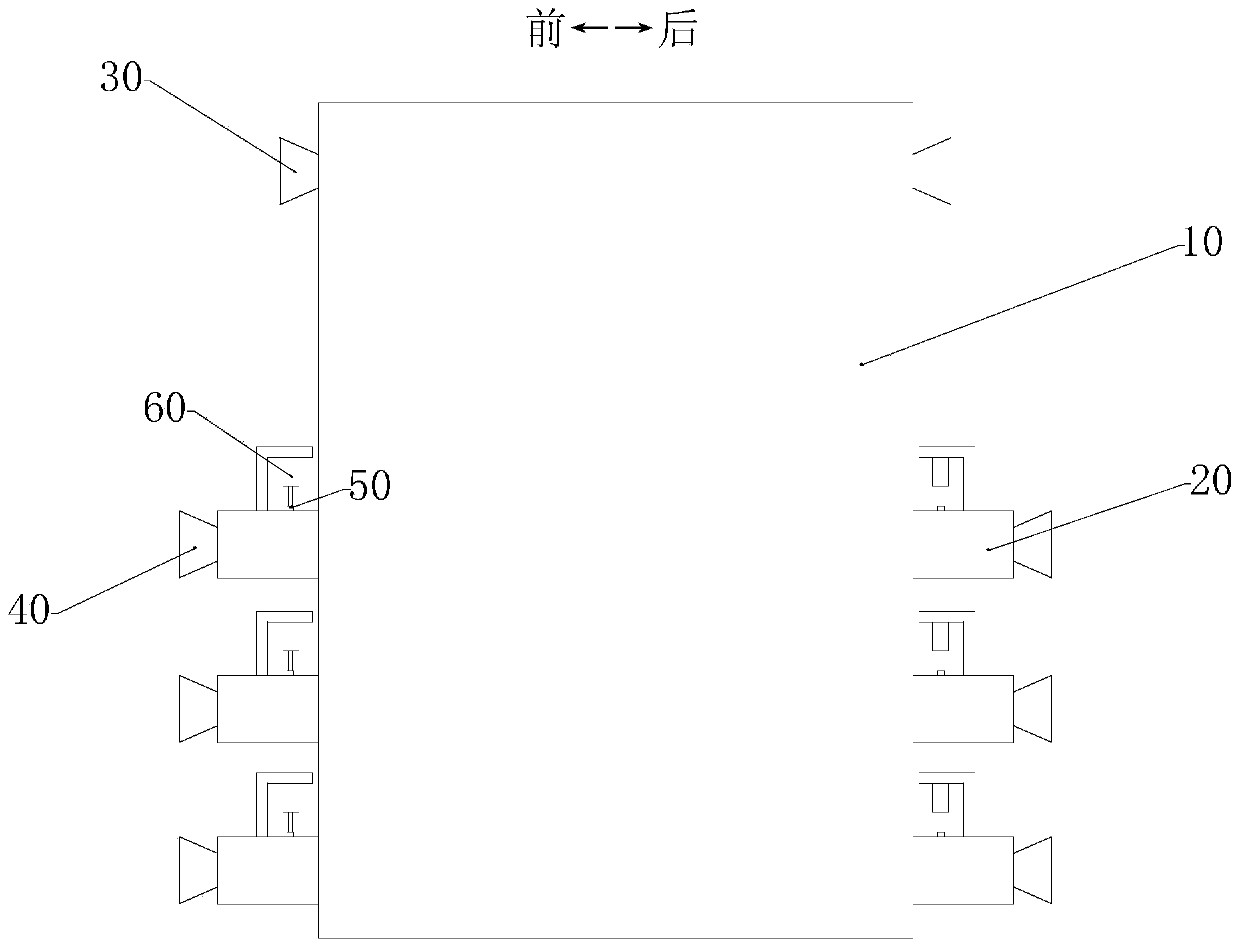
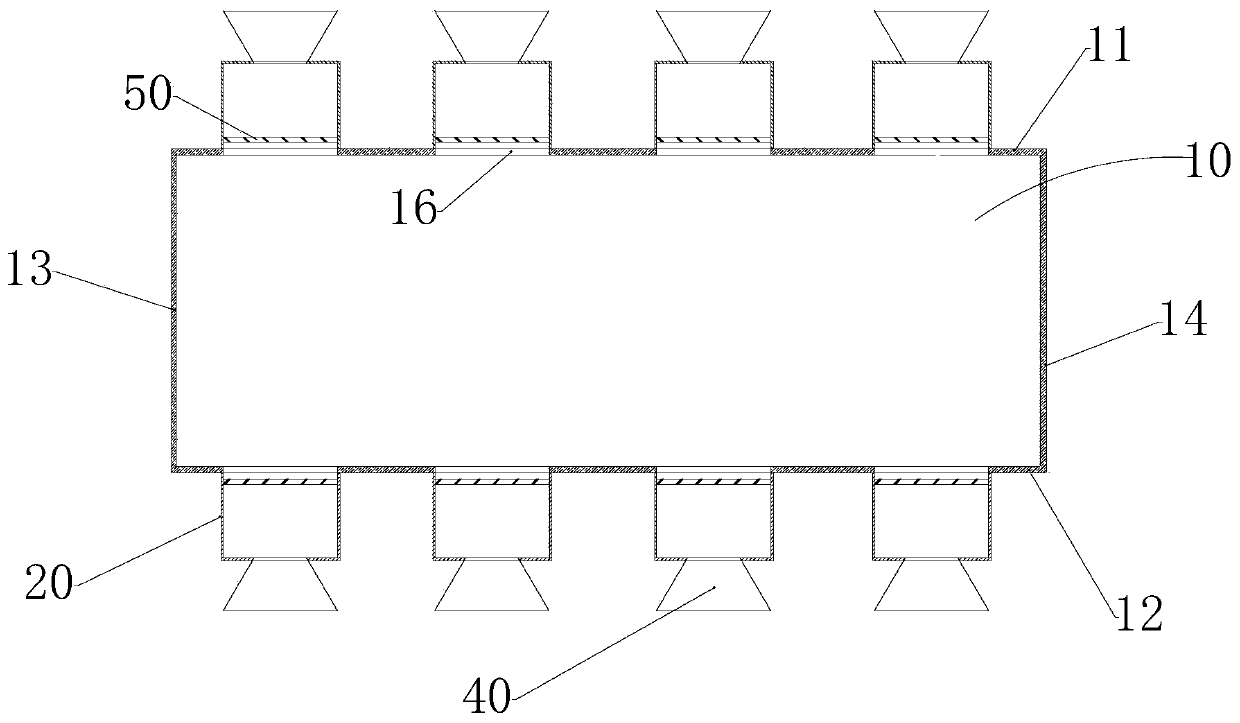
[0035] Under a specific load requirement, the second burner 40 is symmetrically installed on the front side wall 11 and the rear side wall 12 of the boiler 10, and is equidistantly opposed to each other. The additional fuel chamber 20 is a rectangular parallelepiped structure. Correspondingly, the baffle 50 is a rectangular parallelepiped structure, and the length L of the additional fuel chamber 20 along the movement direction of the primary wind is 1.5L 0 , the length d of the additional fuel chamber 20 perpendicular to the movement direction of the primary wind is 0.2H, the opening s of the baffle plate 50 is selected as 50%, L 0 is the ignition distance, and H is the width of the wall of the boiler 10 where the second burner 40 is arranged.

Embodiment 2

[0037] Under another specific load requirement, the second burner 40 is symmetrically installed on the front side wall 11 and the rear side wall 12 of the boiler 10, and is equidistantly opposed to each other. The additional fuel chamber 20 is a cylindrical structure, corresponding to Yes, the baffle plate 50 is a cylindrical structure, and the length L of the additional fuel chamber 20 along the movement direction of the primary wind is 1.5L 0 , the diameter d of the additional fuel chamber 20 perpendicular to the movement direction of the primary wind is 0.2H, the opening s of the baffle plate 50 is selected as 50%, L 0 is the ignition distance, and H is the width of the wall of the boiler 10 where the second burner 40 is arranged.

Embodiment 3

[0039] Under another specific load requirement, the second burner 40 is symmetrically installed on the front side wall 11 and the rear side wall 12 of the boiler 10, and is equidistantly opposed to each other. The additional fuel chamber 20 is a square structure, corresponding to Yes, the baffle plate 50 is a cube-shaped structure, and the length L of the additional fuel chamber 20 along the movement direction of the primary wind is 1.5L 0 , the outlet diameter d of the additional fuel chamber 20 perpendicular to the movement direction of the primary air is 0.2H, the opening s of the baffle plate 50 is selected as 50%, L0 is the ignition distance, and H is the wall surface of the boiler 10 where the second burner 40 is arranged width.


PUM


Abstract

The present invention is an opposed burner system for a supercritical carbon dioxide coal-fired boiler. chamber group, and the first burner is arranged above multiple groups of chamber groups, the first burner is provided with an air outlet, and the position of the boiler corresponding to the first burner is provided with a second A gap, the air outlet on the first burner communicates with the interior of the boiler through the corresponding first gap, each group of chambers includes a plurality of additional fuel chambers, and a plurality of additional fuel chambers The chambers are arranged horizontally, and are arranged on the boiler at even intervals along the left and right directions. The opposing burner system of the invention has the advantages of high combustion efficiency, strong flame stability and the like.

Description

technical field [0001] The invention relates to the field of advanced power generation equipment. More specifically, the present invention relates to an opposed burner system for a supercritical carbon dioxide coal-fired boiler. Background technique [0002] At present, the coal-fired power generation system using water as the circulating working fluid has encountered a bottleneck in improving efficiency. In order to improve the overall efficiency and reduce the heat transfer loss, the parameters of the working fluid cycle can only be continuously increased, but this is limited by the material. It is becoming more and more difficult to find materials that can adapt to high steam parameters and the cost of materials is also increasing. As a result of these circumstances, supercritical CO2 power systems have gained attention. Supercritical carbon dioxide has special physical properties, and the power generation system using it as a working medium has a smaller size and a sma...

Claims


Application Information

Patent Timeline
Patent Type & Authority Patents(China)
IPC IPC(8): F23C5/28F23N1/02
CPCF23C5/28F23N1/02F23C2700/06F23N2237/02F23N2239/02
Inventor 向军朱萌周敬胡松苏胜汪一许凯徐俊何立模韩亨达凌鹏李艾书
Owner HUAZHONG UNIV OF SCI & TECH
Why Eureka
Try Eureka