
LoRa wireless temperature and humidity monitor

A temperature and humidity sensor and monitor technology, applied in wireless communication, instruments, measuring devices, etc., can solve the problems of high cost of data transmission wiring, easy to cause errors, and troublesome manual monitoring.

Inactive Publication Date: 2019-07-12
WUHAN HONGTU ENERGY SAVING TECH
View PDF3 Cites 4 Cited by
  • Summary
  • Abstract
  • Description
  • Claims
  • Application Information

AI Technical Summary

Problems solved by technology

In many occasions, the frequency requirements for temperature monitoring are high, manual monitoring is more troublesome and prone to errors, the use of wired networks for data transmission and wiring costs are high, and later maintenance is difficult, and the use of traditional wifi wireless networks requires high operating costs and the coverage of wifi networks Small

Method used


Image

  • LoRa wireless temperature and humidity monitor
  • LoRa wireless temperature and humidity monitor

Examples


Embodiment 1

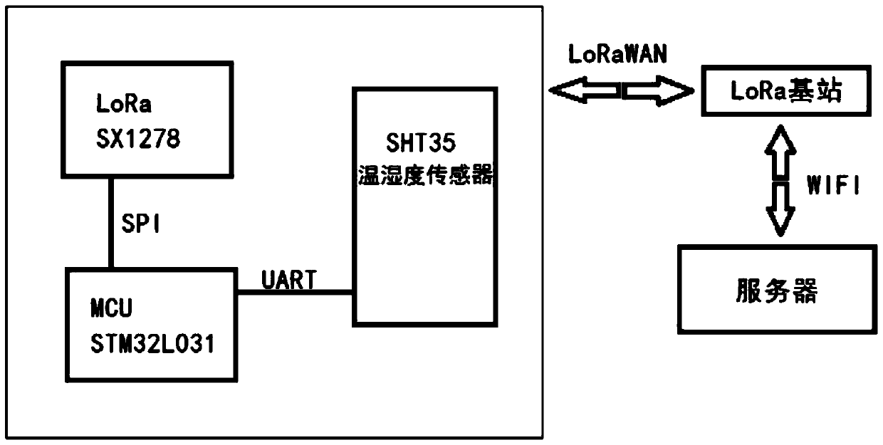
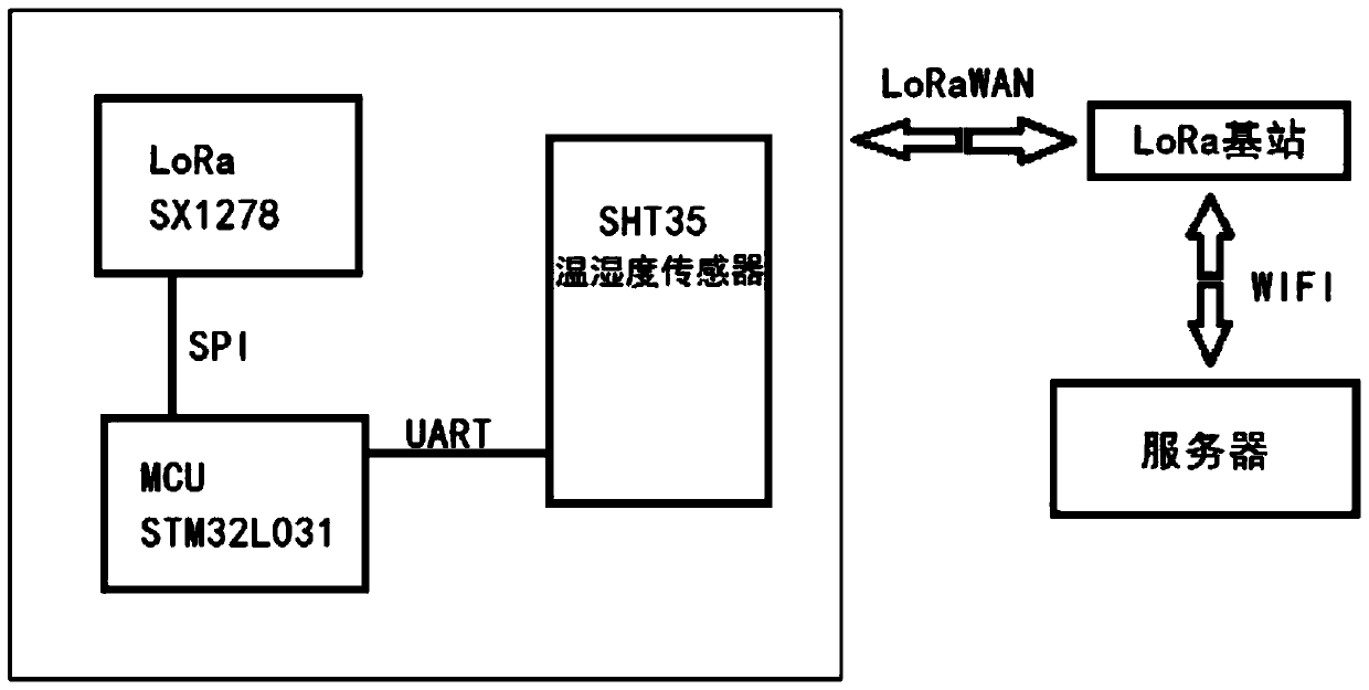
[0021] This embodiment discloses as figure 1 The shown LoRa wireless temperature and humidity monitor includes a main control MCU, a temperature and humidity sensor and a LoRa wireless transmission chip. The temperature and humidity sensor and the main control MCU are connected and communicated through a serial port, and the LoRa wireless transmission chip and the main control MCU are connected and communicated. The communication is connected through SPI; the LoRa wireless transmission chip is connected with the LoRa base station through the LoRaWAN gateway, and the LoRa base station is connected to the monitoring center server through WIFI to realize monitoring.

[0022] The main control MCU is the STM32L031 microcontroller chip. The LoRa wireless transmission chip is the LoRa chip of SX1278 as the wireless transmission chip. After the LoRa base station receives the data, it displays the data on the LCD screen of the LoRa base station, and sends the data to the data backgrou...

Embodiment 2

[0028] The LoRa wireless temperature and humidity monitor in this embodiment adopts an intermittent working mode, collecting data every 10 minutes (which can be configured through the LoRaWAN background). is closed. When it needs to collect data, the MCU wakes up the chip through RTC, and then powers on the temperature and humidity sensor. After the sensor is turned on, it collects data and sends the data to the MCU through the serial port. The MCU wakes up the LoRa chip and sends the data through LoRa.

[0029] The LoRa wireless temperature and humidity monitor uses the STM32L031 single-chip microcomputer chip as the main control MCU, the SX1278 LoRa chip as the wireless transmission chip, plus the SHT35 temperature and humidity sensor, liquid crystal display and battery power supply, and the working voltage is 3.3V.

[0030] The SHT35 temperature and humidity sensor transmits the collected data to the main control MCU chip through the serial port. After the MCU receives the ...


PUM


Abstract

The invention relates to the technical field of environment monitoring. The LoRa wireless temperature and humidity monitor comprises a main control MCU, a temperature and humidity sensor and a LoRa wireless transmission chip, the temperature and humidity sensor is connected and communicated with the main control MCU through a serial port, and the LoRa wireless transmission chip is connected and communicated with the main control MCU through an SPI; wherein the LoRa wireless transmission chip is connected with the LoRa base station through the LoRa WAN gateway, and the LoRa base station is communicated with the monitoring center server through WIFI to realize monitoring; according to the invention, the LoRaWAN network is mainly used for data transmission. The detector adopts the MCU + LoRa+ temperature and humidity sensor mode design, the main control chip sends data collected by the sensor out through the LoRa chip, the data are uploaded to the background through the LoRa base stationand finally sent to the monitoring mechanism to be used for monitoring the environment temperature and humidity so as to meet special environment requirements, and high creativity is achieved.

Description

technical field [0001] The invention relates to the technical field of environmental monitoring, in particular to a LoRa wireless temperature and humidity monitor. Background technique [0002] With the development of production technology and science and technology, people have more and more needs for environmental monitoring. For example, in vegetable cultivation, spinach and onion grow best at 15-20°C, and pumpkin and wax gourd grow best at around 30°C. In the warehousing industry, the storage conditions of medicines are required to be in a cold room (2-10 ℃), a cool warehouse (below 20 ℃) ​​or a normal temperature warehouse (0-30 ℃), and the relative humidity of each warehouse should be maintained at 45%-75 %, in daily life, the suitable temperature for babies is about 26 ℃ in summer and about 20 ℃ in winter; in the breeding industry, the suitable temperature for raising pigs is 16-20 ℃, and the relative humidity is 65%-75%. The indoor temperature is 27°C for chicks and...

Claims


Application Information

Patent Timeline
Patent Type & Authority Applications(China)
IPC IPC(8): H04W84/18H04L29/08G08C17/02G01D21/02
CPCG01D21/02G08C17/02H04L67/12H04W84/18
Inventor 桂正虎黄绍伟
Owner WUHAN HONGTU ENERGY SAVING TECH
Learn More