Automatic feeding and stirring tank truck
An automatic feeding and tanker technology, which is applied to cement mixing devices, unloading devices, clay preparation devices, etc., can solve the problems of unloading structures that are not easy to load and unload, easy to damage hydraulic cylinders, and material splashing, etc. Easy to control, eliminate collision force, reduce the effect of rake angle
- Summary
- Abstract
- Description
- Claims
- Application Information
AI Technical Summary
Problems solved by technology
Method used
Image
Examples
Embodiment 1
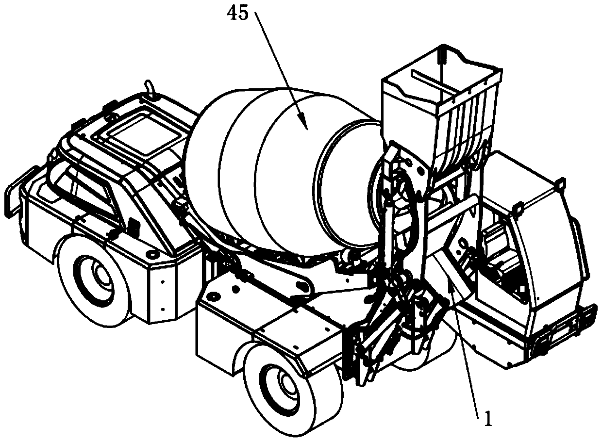
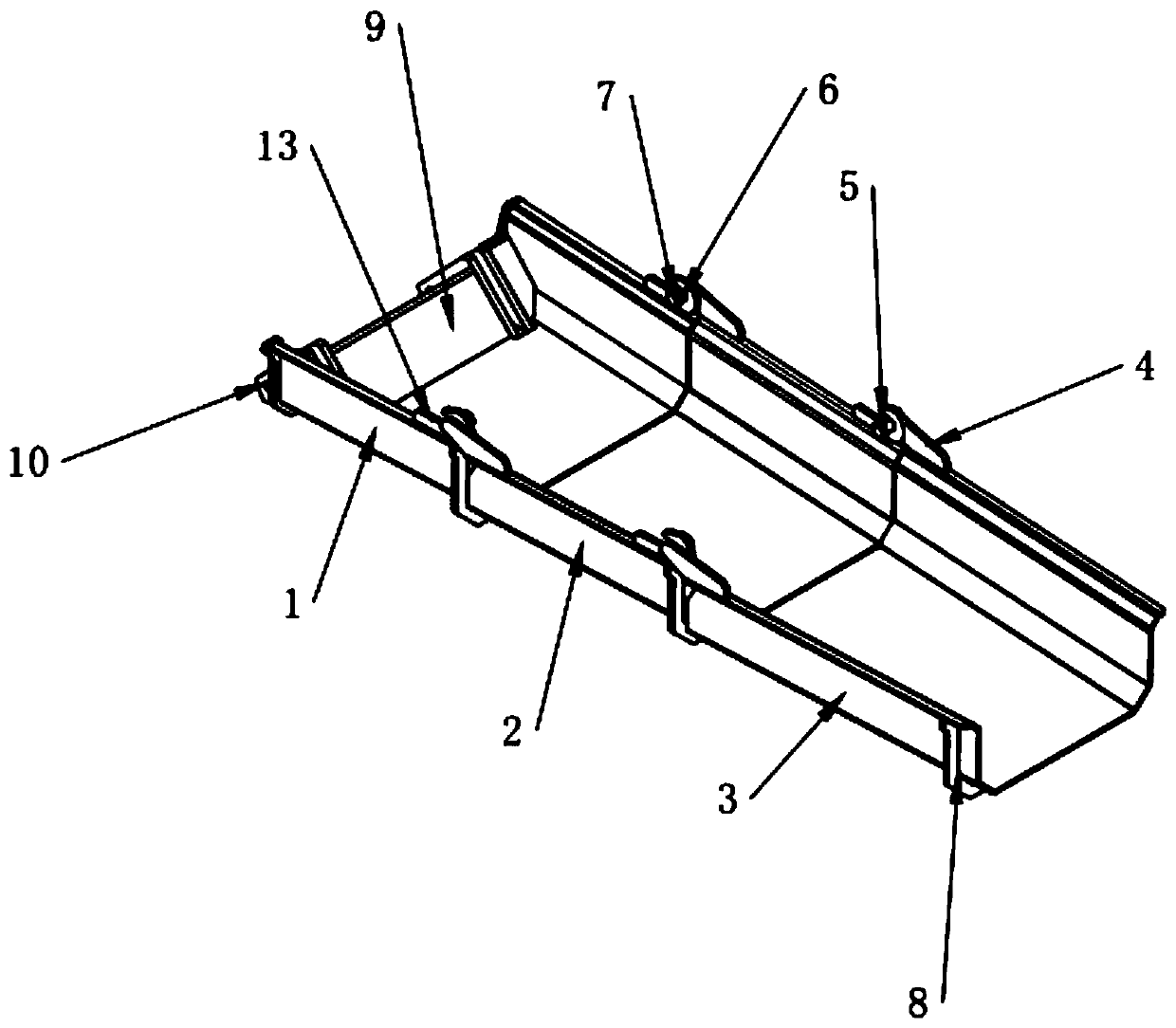
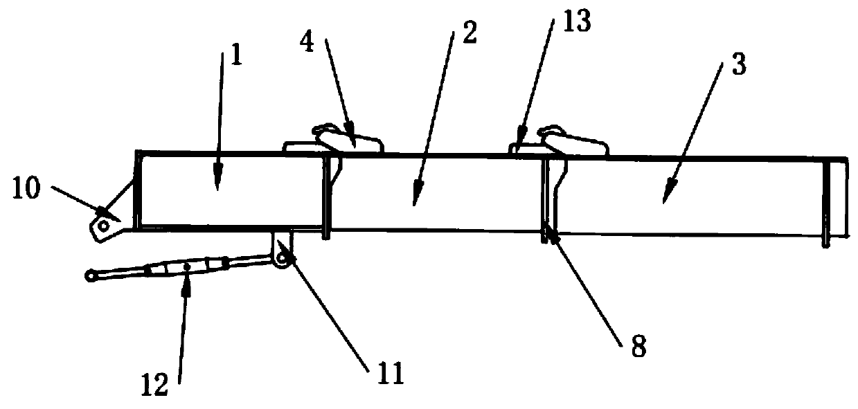
[0087] Such as Figure 1 to Figure 12 As shown, the automatic feeding mixing tank car includes a support seat protection mechanism, a self-compensating support mechanism, a self-unloading mechanism and a guide unloading mechanism; the support seat protection mechanism includes mutually hinged bogies 14, and is arranged on the bogies 14 for A cushioning component that prevents rigid collisions when turning.
[0088] The self-compensating support mechanism includes a support frame 29, on which two support wheels 37 are arranged side by side, and the two support wheels 37 perform self-oscillating motions along their axis directions.
[0089] The self-discharging mechanism includes a bucket, and the first bottom plate 19 and the first top plate 18 of the bucket are set in a tapered manner along the feeding direction, and the discharge end transition of the first bottom plate 19 is fixedly connected with a load bearing extending obliquely upward. plate, the discharge end of the fi...
Embodiment 2
[0131] Such as Figure 13 with Figure 14 As shown, the difference between this embodiment and Embodiment 1 lies in the discharge mode of the self-discharging mechanism; this embodiment is a jaw type self-discharging bucket, including a bucket, the second bottom plate 48 and the second top plate of the bucket 47 is tapered along the feeding direction, and the discharge end transition of the second bottom plate 48 is fixedly connected with the first material guide plate 59 extending upwardly, and the discharge end of the second top plate 47 is connected with the first material guide. The second discharge opening 55 is formed between the upper ends of the plates 59, and the two side walls of the bucket are in the part connected with the first material guide plate 59 and are tapered along the feeding direction. The second discharge opening 55 A second unloading plate 58 for controlling the opening and closing of the second unloading port 55 is provided on the side.
[0132] An ...
Embodiment 3
[0144] Such as Figure 15 with Figure 16 As shown, the difference between this embodiment and Embodiments 1 and 2 is also the discharge mode of the self-discharging mechanism; this embodiment is a load-bearing self-discharging bucket, including a bucket, the third bottom plate 61 of the bucket and The third top plate 60 is tapered along the feeding direction, and the discharge end of the third bottom plate 61 is transitionally connected with a second material guide plate 72 extending upwards, and between the discharge end of the third top plate 60. The third discharge port 68 is formed between them. The two side walls of the bucket are located at the part connected with the second material guide plate 72 and are tapered along the feeding direction. The two side walls of the third discharge port 68 are also fixed. An arc-shaped guide plate 62 is connected, and a third discharge plate 71 for controlling the opening and closing of the third discharge opening 68 is fitted and sl...
PUM
 Abstract
Description
Claims
Application Information
 - R&D
- Intellectual Property
- Life Sciences
- Materials
- Tech Scout
- Unparalleled Data Quality
- Higher Quality Content
- 60% Fewer Hallucinations
Browse by: Latest US Patents, China's latest patents, Technical Efficacy Thesaurus, Application Domain, Technology Topic, Popular Technical Reports.
© 2025 PatSnap. All rights reserved.Legal|Privacy policy|Modern Slavery Act Transparency Statement|Sitemap|About US| Contact US: help@patsnap.com


