
Apparatus for fixing vehicle roof bar

A technology of fixing devices and ejector rods, which is applied to vehicle parts, locking fasteners, transportation and packaging, etc. It can solve the problems of difficulty, easy separation, and difficult installation by ordinary people, and achieve the effect of easy installation or disassembly

Inactive Publication Date: 2019-07-09
尹一植 +1
View PDF6 Cites 0 Cited by
  • Summary
  • Abstract
  • Description
  • Claims
  • Application Information

AI Technical Summary

Problems solved by technology

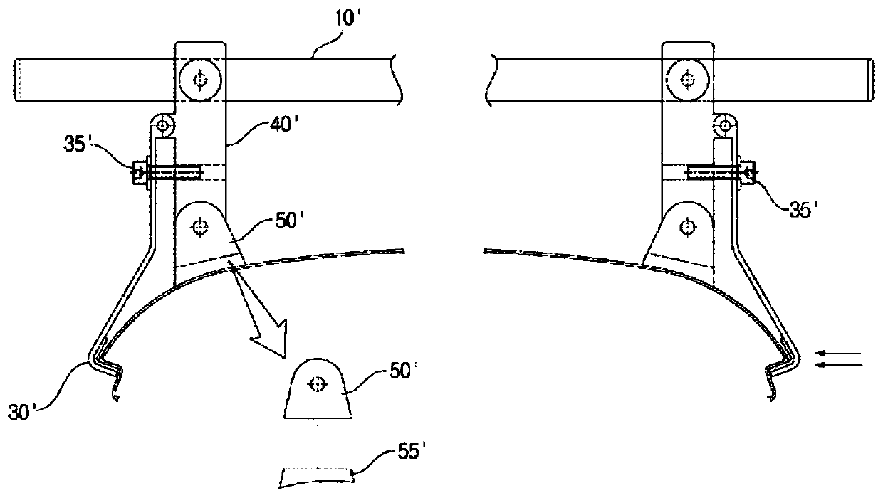
Moreover, when fixing the ejector rod 10', if the center correction is not accurately performed so that the left and right side support brackets are accurately arranged at the same position, the ejector rod cannot be positioned at a right angle to the longitudinal axis of the vehicle, and when the impact is received during driving, or external force, it will be easy to separate
[0006] That is, in the past, if it is desired to fix the ejector bar 10' on the roof of the vehicle, it is difficult for ordinary people to install it due to the difficulty of centering work on the left and right sides. When performing the installation work, additional tools such as hexagonal wrenches are required.

Method used


Image

  • Apparatus for fixing vehicle roof bar
  • Apparatus for fixing vehicle roof bar
  • Apparatus for fixing vehicle roof bar

Examples


Embodiment Construction

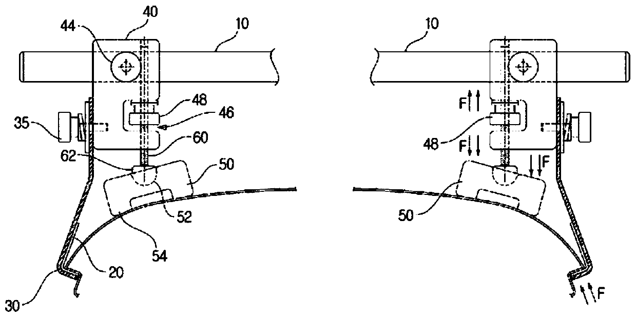
[0019] figure 2 It is a cross-sectional view of the left and right sides of the roof of the roof rod fixing device of the present invention.

[0020] As shown in the figure, the ejector rod fixing device of the present invention is also arranged on both side door frames and the roof portion of the automobile.

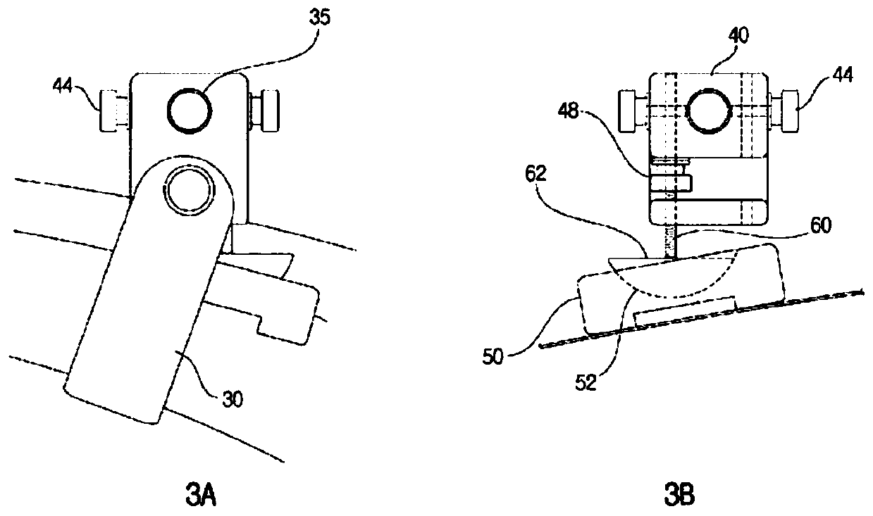
[0021] The automobile ejector rod fixing device of the present invention comprises ejector rod 10, cushioning material 20, hook 30, bracket 40, bracket 50 and half-moon head bolt 60, and the remaining parts except ejector rod 10 all form a set of two parts.

[0022] Such as figure 2 As shown on the left side of , the ejector rod 10 is a long rod-shaped member arranged laterally at intervals on the roof.

[0023] When the ejector rod 10 is fixed, in order to prevent scratches or damages on the surface of the vehicle, the cushioning material 20 is closely attached to the window frame of the vehicle. The section of the cushioning material is L-shaped and formed of an e...


PUM


Abstract

The present invention relates to an apparatus, for fixing a vehicle roof bar, comprising: a long roof bar (10) horizontally disposed on a vehicle roof with a gap therebetween and having screw threadsformed on both end parts; two cushioning materials (20) which come in close contact with both window frames of a vehicle, respectively, have an L-shaped cross section, and comprise a resilient material; two hooks (30) which are respectively fixed to both window frames, of the vehicle, with the cushioning material (20) therebetween, have an L-shaped cross section, and comprise metal or hard plastic; two brackets (40) which have both end parts of the roof bar (10) passing therethrough and protruding, have the outer lateral sides being supported by the two hooks (30), respectively, are fixed upright on the vehicle roof with a gap therebetween, and have a staple-shaped cross section; two supports (50) which are supported on the vehicle roof, have a dome-shaped groove (52), having a semicircular cross section, on the upper end part, are positioned right below the brackets (40), have a plurality of protruding portions (54) on the lower end, and comprise a resilient material; and two dome-headed bolts (60) which have a dome head (62) having a semicircular cross section and being inserted into the groove (52) of the support (50), have a screw thread formed on a body, and are screw-coupledto the roof bar (10) by means of the brackets (40) when assembled.

Description

technical field [0001] The invention relates to a jack rod fixing device for an automobile, in particular to a jack rod fixing device for an automobile which can be easily installed by ordinary people. Background technique [0002] Usually, the roof bar of the car is fixed to the roof by means of pressure applied from both sides and by means of brackets on both sides. [0003] figure 1 It is a sectional view showing an example of a conventional ejector pin fixing device, and the left side and the right side are shown. [0004] As shown in the figure, in the conventional case, a buffer pad 55' is provided below a bracket 50' that rotatably supports a bracket 40', and the bracket 40' supports the ejector rod 10' so that the buffer pad 55' supports it. On the roof surface, the hook 30' is fixed to the bracket 40' from the side by tightening the fixing bolt 35' to the hook 30' fixed to the window frame of the vehicle. In the accompanying drawings, as shown by the arrows, brac...

Claims


Application Information

Patent Timeline
Patent Type & Authority Applications(China)
IPC IPC(8): B60R9/058F16F1/18F16B35/06F16B39/24
CPCB60R9/058F16B35/06F16B39/24F16F1/18B60R9/052
Inventor 尹一植尹准攒
Owner 尹一植
Learn More