Generator set cooling air duct structure

A technology for cooling air ducts and generator sets, which is applied in the direction of engine cooling, cooling/ventilation devices, electric components, etc., which can solve the problems of poor cooling effect, loud noise, etc., and achieve the goal of optimizing the cooling path and improving the cooling effect Effect

Pending Publication Date: 2019-07-09
重庆华世丹动力科技有限公司
View PDF0 Cites 4 Cited by
  • Summary
  • Abstract
  • Description
  • Claims
  • Application Information

AI Technical Summary

Problems solved by technology

On the other hand, a large noise will be generated during the working process of the generator set, which will endanger the normal life of users and other people. In order to reduce the noise, the common method is to make it an all-inclusive (that is, fully enclosed) structure, but now Some all-inclusive generator sets usually only have the first air duct for cooling the engine cylinder head. Even if some existing structures are equipped with a second air duct for cooling the bottom of the engine, there is still a defect of poor cooling effect. The output power of the generating set is low and the noise is large

Method used


Image

  • Generator set cooling air duct structure
  • Generator set cooling air duct structure
  • Generator set cooling air duct structure

Examples


Embodiment Construction

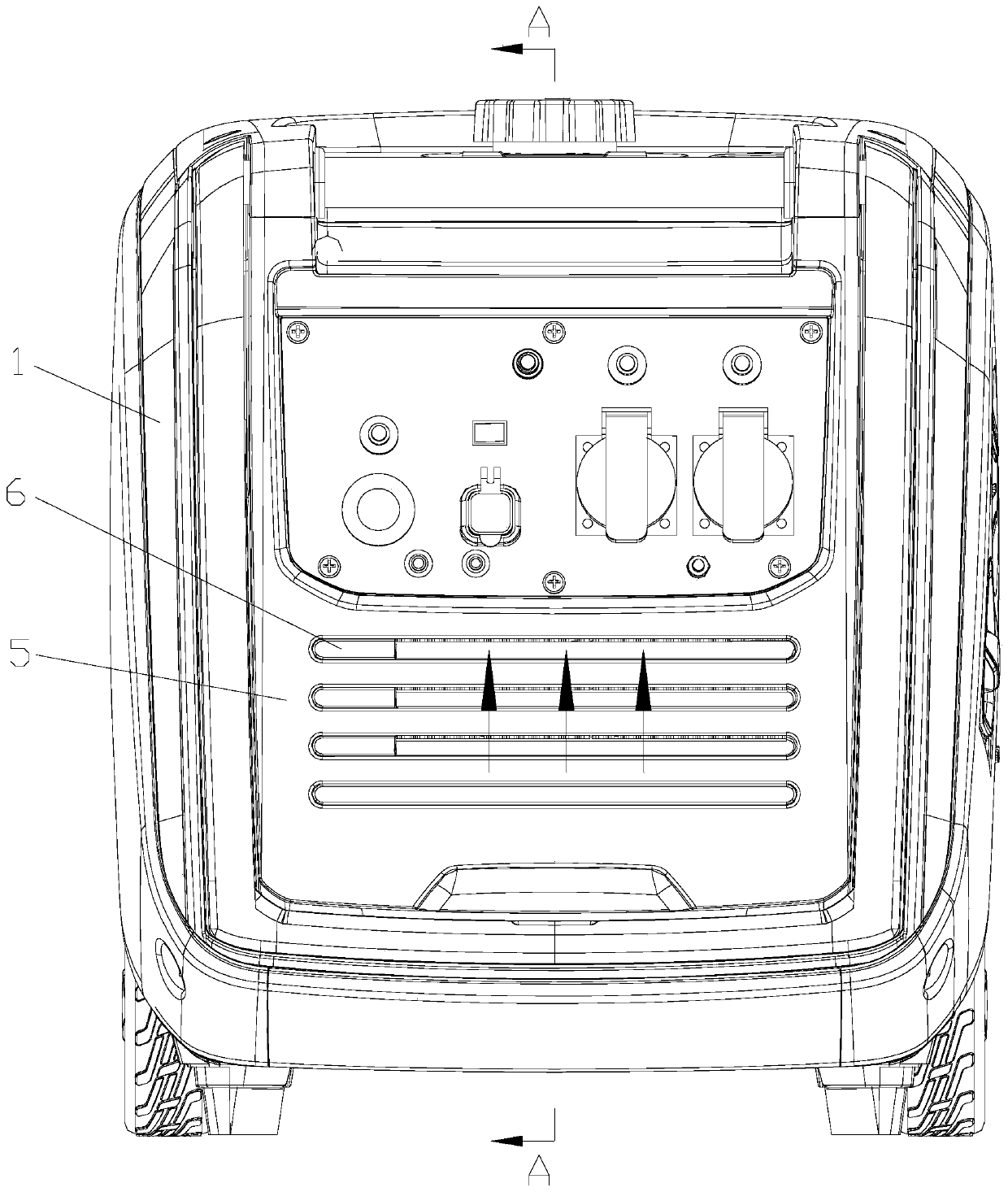
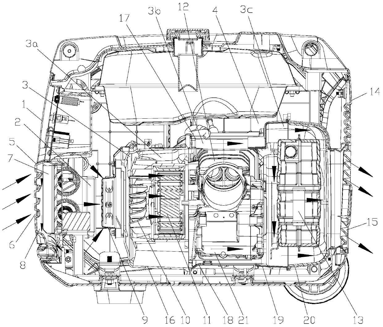
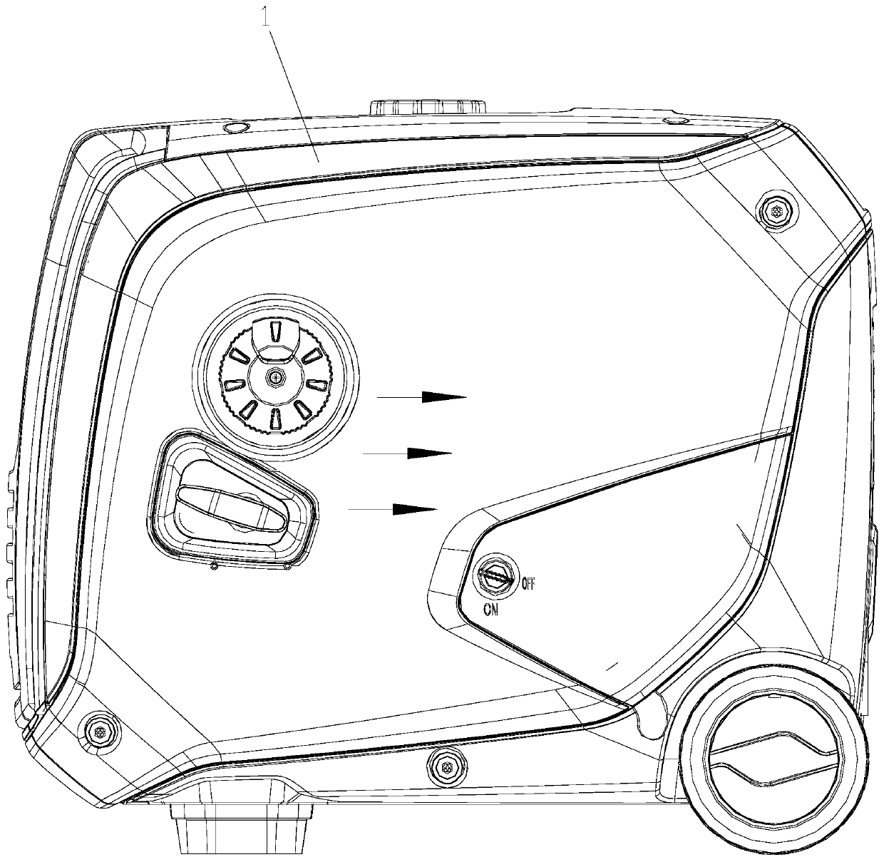
[0021] like Figure 1 to Figure 4 As shown: the structure of the cooling air duct of the generator set in this embodiment includes a housing 1 with an inner cavity. The front and rear sides of the inner cavity of the housing 1 are respectively opened to form an air inlet side and an air outlet side. The inner cavity An air guide assembly is arranged inside, and cooling passages respectively connected with the air inlet side and the air outlet side are formed inside the air guide assembly, and the impeller 10, the generator 11. The engine 12 and the muffler 13, the cooling channel includes the cooling air channel I3 passing through the air inlet side and the air outlet side and the cooling air channel II21 formed between the bottom of the engine 12 and the air guide assembly, the outer wall of the air guide assembly Cooling air passages III4 for cooling the side and top of the engine are formed between the two sides and the top and the inner cavity wall of the housing 1. The co...


PUM


Abstract

The invention discloses a generator set cooling air duct structure. The structure comprises a shell with an inner cavity, wherein the front side and the rear side of the inner cavity are opened to form an air inlet side and an air outlet side respectively, an air guide assembly is arranged in the inner cavity, cooling channels communicating with the air inlet side and the air outlet side are formed in the air guide assembly, an impeller, a generator, an engine and a silencer are sequentially arranged in the cooling channels from the air inlet side to the air outlet side, the cooling channels comprise the cooling air duct I penetrating through the air inlet side and the air outlet side, and the cooling air duct II formed between the bottom of the engine and the air guide assembly, a coolingair duct III used for cooling the side part and the top of the engine is formed between the two sides of the outer wall of the air guide assembly and the cavity wall of the inner cavity of the shell,and the cooling air duct III communicates with the air inlet side and the air outlet side. The cooling effect can be greatly improved, so that the output power of a generator set is improved, and thenoise is reduced at the same time.

Description

technical field [0001] The invention relates to the field of generator sets, in particular to a cooling air duct structure of a generator set. Background technique [0002] The generator set is mainly composed of an engine, a generator, a frequency converter, a muffler and other auxiliary devices, which can convert the chemical energy of fuel into electrical energy, and have a wide range of applications, such as: field operations, emergency electricity, disaster relief, outdoor life and travel , yachts and vehicles with their own power supply, mobile communication base stations and many other occasions. Since the engine converts the chemical energy released by combustion into mechanical energy during the working process of the generator set, and the generator converts the mechanical energy into electrical energy, both of them will generate a lot of heat energy during the working process, and the inverter itself will also To generate a certain amount of heat, in order to ens...

Claims


Application Information

Patent Timeline
IPC IPC(8): F02B63/04F01P1/00F01N13/00H02K9/04
CPCF02B63/04F01P1/00F01N13/007H02K9/04
Inventor 杨全王虎山杜靖华闫晓军兰锐
Owner 重庆华世丹动力科技有限公司
Why Eureka
Try Eureka