Reinforced concrete shear wall and construction method thereof
A reinforced concrete and shear wall technology, applied in the direction of walls, building components, buildings, etc., can solve the problems of injury to construction workers, cumbersome dismantling of nails, unsatisfactory use, etc., to avoid injuries, simple disassembly steps, and save time. Effect
- Summary
- Abstract
- Description
- Claims
- Application Information
AI Technical Summary
Problems solved by technology
Method used
Image
Examples
Embodiment 1
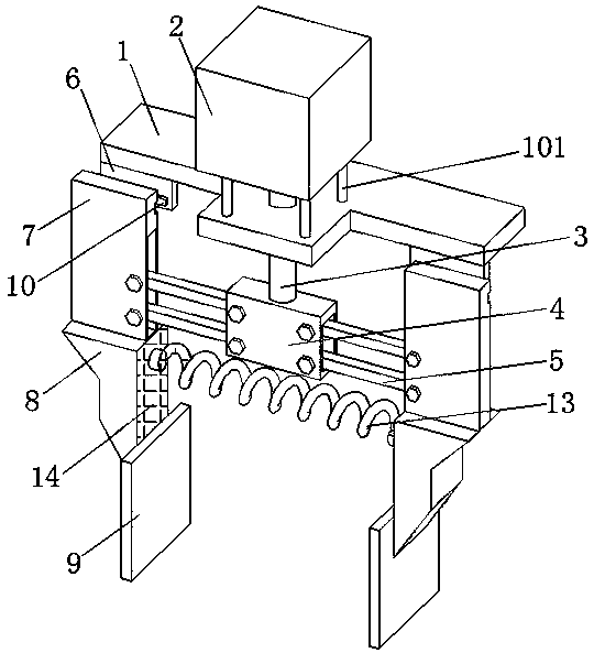
[0026] refer to Figure 1-2 , a reinforced concrete shear wall, comprising a first fixed plate 1, the top of the first fixed plate 1 is connected with a support rod 101, the top of the support rod 101 is connected with a cylinder 2, the output end of the cylinder 2 is connected with a pull rod 3, the first The top of the fixed plate 1 is drilled with a through hole matched with the pull rod 3, and the end of the pull rod 3 away from the cylinder 2 passes through the through hole and is connected with the connection box 4, and the inner walls on both sides of the connection box 4 are rotatably connected with the connection rod 5. Both ends of the first fixed plate 1 are fixedly connected with a second fixed plate 6, the outer walls of the two second fixed plates 6 are slidably connected with a sliding plate 7, and the end of the connecting rod 5 away from the connection box 4 is connected to the sliding plate 7 in rotation, The bottom of the sliding plate 7 is connected with a ...
Embodiment 2
[0028] refer to Figure 1-4 , a reinforced concrete shear wall, which is basically the same as Embodiment 1, furthermore, the outer wall of the second fixed plate 6 is connected with a slide rail 10, and the outer wall of the slide plate 7 is dug with a groove 11 matching the slide rail 10 ; Under the pull of the connecting rod 5, the sliding plate 7 makes the slide rail 10 slide in the groove 11 more conveniently, which is conducive to the smooth sliding of the device.
[0029] The outer walls of the two splints 8 are connected with a fixed block 12, and a spring 13 is connected between the two fixed blocks 12; using the elastic characteristics of the spring 13, the splint 8 can be avoided in the process of tightening the wooden formwork 9 by the splint 8. 2 directly acts on wooden formwork 9 under the effect of 2, plays certain cushioning and damping function.
Embodiment 3
[0031] refer to Figure 1-4 , a reinforced concrete shear wall, which is basically the same as Embodiment 1, furthermore, the outer wall of the splint 8 is connected with a rubber pad 14, the outer wall of the rubber pad 14 is provided with anti-skid lines, and the rubber pad 14 is offset against the wooden formwork 9; Protect the wooden formwork 9 to prevent the wooden formwork 9 from being damaged due to being squeezed during the clamping process, and the outer wall of the rubber pad 14 is provided with anti-skid lines, which can prevent the wooden formwork 9 from shaking during the clamping process , which is beneficial to the device to better complete the clamping work.
[0032] The wooden formwork 9 is made of bamboo plywood; this formwork has high strength and good toughness, and the static bending strength of the board is equivalent to eight to ten times the strength of wood, which can reduce the number of supports used, and the bamboo plywood has a wide width, few join...
PUM
 Abstract
Description
Claims
Application Information
 - R&D
- Intellectual Property
- Life Sciences
- Materials
- Tech Scout
- Unparalleled Data Quality
- Higher Quality Content
- 60% Fewer Hallucinations
Browse by: Latest US Patents, China's latest patents, Technical Efficacy Thesaurus, Application Domain, Technology Topic, Popular Technical Reports.
© 2025 PatSnap. All rights reserved.Legal|Privacy policy|Modern Slavery Act Transparency Statement|Sitemap|About US| Contact US: help@patsnap.com


