
Underwater plankton optical imaging device and method

A technology of optical imaging and plankton, applied in image communication, TV, color TV parts, etc., can solve the problems of increased total power consumption, extended working hours, low power density of LED lighting, etc., to improve contrast and signal Noise ratio, the effect of reducing system power consumption

Active Publication Date: 2019-07-05
SHENZHEN INST OF ADVANCED TECH CHINESE ACAD OF SCI +1
View PDF6 Cites 11 Cited by
  • Summary
  • Abstract
  • Description
  • Claims
  • Application Information

AI Technical Summary

Problems solved by technology

[0009] However, as an incoherent light source, LED light source still has its shortcomings
First of all, its divergence angle is still relatively large. When it is applied to an underwater imaging device with high resolution requirements, it is difficult to spatially limit the light emitted by the LED to a shallow depth of field, resulting in particles outside the focal plane. Illuminated and collected by the imaging device, resulting in decreased image contrast
Secondly, because the power density of LED lighting is still low, when using it to realize flash lighting, in order to ensure that the brightness of the lighting moment is strong enough, it needs to be driven with a large pulse current
This not only requires a dedicated drive circuit, but also leads to increased total power consumption, which is not conducive to the reliability of the underwater in-situ observation system and to prolong the working time

Method used


Image

  • Underwater plankton optical imaging device and method
  • Underwater plankton optical imaging device and method
  • Underwater plankton optical imaging device and method

Examples


Embodiment Construction

[0058] Below, the implementation of the technical solution will be further described in detail in conjunction with the accompanying drawings.

[0059] Those skilled in the art can understand that although the following description involves many technical details related to the embodiments of the present invention, this is only an example for illustrating the principle of the present invention, and does not imply any limitation. The present invention can be applied to occasions other than the technical details exemplified below, as long as they do not deviate from the principle and spirit of the present invention.

[0060] In addition, in order to avoid making the description in this manual limited to redundant, in the description in this manual, some technical details that can be obtained in the existing technical documents may be omitted, simplified, modified, etc. understandable to human beings, and this does not affect the adequacy of the disclosure of this specification. ...


PUM


Abstract

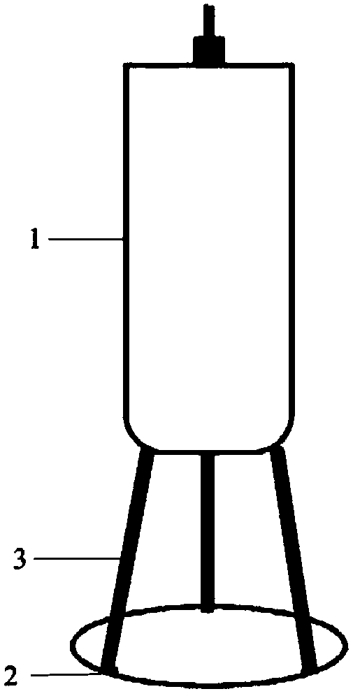
The invention relates to an underwater plankton optical imaging device and method, and the device comprises an optical imaging unit (1) which is used for collecting scattered light or fluorescence emitted by an underwater plankton irradiated by a laser illumination unit, and carrying out the imaging of the underwater plankton; the laser lighting unit (2) comprises a laser lighting module and is used for lighting the underwater imaging area; wherein the laser illumination module emits a fan-shaped light layer to the illumination center to carry out imaging illumination. Compared with an existing device and method, the contrast ratio and the signal to noise ratio of underwater plankton imaging can be improved, and follow-up plankton identification and quantification based on image analysis are facilitated; in addition, the application mode and application scene of underwater plankton optical imaging can be expanded, meanwhile, the power consumption of the system is reduced, and compactness, miniaturization and intelligentization of the system are achieved.

Description

technical field [0001] The invention relates to the field of underwater optical instruments, in particular to an underwater plankton optical imaging device and method. Background technique [0002] Plankton is a fundamental component of the marine ecosystem and plays an important role in the material cycle and energy transfer of the marine food chain. The study of physiology, ecology, diversity and processes of plankton is an essential part of understanding marine resources, biodiversity levels, and the impact of climate change on ecosystems. [0003] At present, the observation of marine plankton mostly relies on traditional manual methods such as network sampling combined with microscope inspection, and its degree of automation is difficult to meet the high time resolution requirements of marine microscopic organism observation. As one of the recognized development trends of ocean observation, in situ observation technology can measure marine plankton in situ underwater, ...

Claims


Application Information

Patent Timeline
Patent Type & Authority Applications(China)
IPC IPC(8): H04N5/225H04N5/235
CPCH04N23/50H04N23/56H04N23/54H04N23/55H04N23/74
Inventor 李剑平陈涛章逸舟刘鹏陈良培
Owner SHENZHEN INST OF ADVANCED TECH CHINESE ACAD OF SCI
Learn More