
Cable sealing clamping and shielding woven layer compaction one-key tail clamp

A cable sealing and cable shielding technology, which is applied in the direction of connection, parts of connecting devices, devices for reducing the stress at the connection of wires, etc. , to achieve the effect of improving assembly efficiency, shortening assembly time and high reliability

Pending Publication Date: 2019-07-05
CHINA AVIATION OPTICAL-ELECTRICAL TECH CO LTD
View PDF0 Cites 5 Cited by
  • Summary
  • Abstract
  • Description
  • Claims
  • Application Information

AI Technical Summary

Problems solved by technology

[0011] In order to solve the problems of low assembly efficiency of the existing connector tail clips, loosening and retreating of the tail clip screws, secant line damage, and large space occupation, the present invention proposes a cable sealing, cable clamping, and cable shielding braiding layer compression One-button realization of the tail clamp with other functions, abandoning the screw clamping structure at the end of the existing tail clamp, making the structure of the tail clamp more compact, more convenient to operate, and higher in reliability

Method used


Image

  • Cable sealing clamping and shielding woven layer compaction one-key tail clamp
  • Cable sealing clamping and shielding woven layer compaction one-key tail clamp
  • Cable sealing clamping and shielding woven layer compaction one-key tail clamp

Examples


Embodiment Construction

[0034] The technical solutions of the present invention will be further described in detail below in conjunction with the accompanying drawings and preferred embodiments. In this embodiment, the position where the connector housing 13 is located is defined as "front", and the position where the tail clip nut 12 is located is defined as "rear".

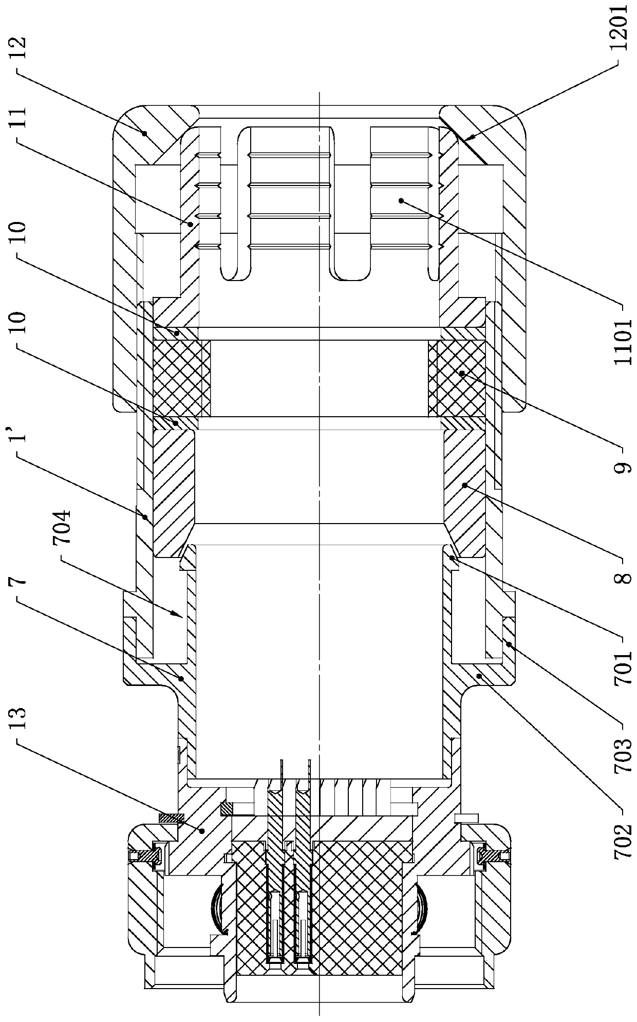
[0035] see image 3 , based on the working environment requirements of high temperature, high radiation, and high sealing performance, the present invention proposes a cable sealing, cable clamping, and cable shield braiding layer pressing one-key realization type connector tail clamp, including sleeve 1', transfer welding Cylinder 7, shielding ring 8, rubber ring 9, gasket 10, clamping ring 11 and tail clip nut 12.

[0036] Sleeve 1' is used as the end clamp housing, which is used to assemble the transfer welding cylinder, shielding ring, rubber ring, clamping ring and end clamp nut distributed in sequence along the axial direction. ...


PUM


Abstract

The cable sealing clamping and shielding woven layer compaction one-key tail clamp comprises a sleeve, a shielding ring and a rubber ring which are successively arranged in the sleeve in the axial direction, a line clamping ring having a plurality of claws arranged at its rear end in the circumferential direction. The front end of the sleeve is welded and fixed to a mounting portion protruding from the outer wall of a spin welding sleeve. A tail clamp nut is detachably mounted on the rear end of the sleeve. When mounted, the tail clamp nut is movable in the axial direction of the sleeve to beabutted against the rear end of the line clamping ring such that each claw retracts inwardly in the radial direction to clamp a cable passing through the sleeve, and applies axial pressure to the rubber ring to cause radial deformation to seal the cable passing through the sleeve. The axial pressure is applied to the shielding ring in order that the conical surface at the front end of the inner wall of the shielding ring matches the conical surface of the boss at the rear end of the spin welding sleeve to compact a cable shielding woven layer. The tail clamp can realize functions of cable shielding woven layer compaction, cable sealing, cable clamping and the like by assembling the tail clamp nut, thereby shortening the assembly time and improving the assembly efficiency.

Description

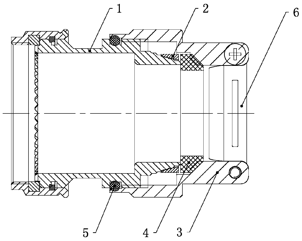
technical field [0001] The invention belongs to the technical field of electrical connection devices, and in particular relates to a one-button connector end clamp with functions such as cable sealing, cable clamping, and cable shield braiding layer compression, and a connector using the end clamp. Background technique [0002] At present, the tail clips of electrical connectors are generally required to have a cable shielding braided layer compression function structure, a cable sheath sealing function structure, and a cable tensile and anti-pull function structure. by figure 1 , figure 2 Take the electrical connector tail clip shown as an example. The operation and use of the tail clip are as follows: [0003] (1) The cable shielding layer needs to be pre-pressed between the end of the sleeve 1 and the compression ring 2; [0004] (2) The tail clamp housing 3 is screwed and tightened, and the tail clamp housing is driven forward by the screw thread to compress the axia...

Claims


Application Information

Patent Timeline
Patent Type & Authority Applications(China)
IPC IPC(8): H01R13/59H01R13/52H01R13/648H01R13/504
CPCH01R13/504H01R13/5205H01R13/59H01R13/648
Inventor 牛志军杜俊伟江浪薛欢欢赵鹏坤
Owner CHINA AVIATION OPTICAL-ELECTRICAL TECH CO LTD
Learn More