Eureka AIR delivers breakthrough ideas for toughest innovation challenges, trusted by R&D personnel around the world.

Diaphragm wall construction method

A technology of underground diaphragm wall and construction method, which is applied in sheet pile wall, foundation structure engineering, earth mover/shovel, etc., can solve the problems of exposed reinforcement quality defect of steel cage, poor concrete fluidity, exposed steel cage, etc. Achieve the effect of increasing the range of vibration, uniform distribution of concrete, and enhanced fluidity

Inactive Publication Date: 2019-07-05
SHANGHAI YUANFANG GROUNDWORK ENG
View PDF0 Cites 1 Cited by
  • Summary
  • Abstract
  • Description
  • Claims
  • Application Information

AI Technical Summary

Problems solved by technology

This results in poor fluidity of the concrete in the reinforcement cage, especially from the inside to the outside of the reinforcement cage.
Therefore, the poured concrete in the prior art is often difficult to flow to the outside of the reinforcement cage, which causes the reinforcement cage to be exposed and is easily corroded, resulting in quality defects of the reinforcement cage exposed reinforcement after excavation of the foundation pit, causing major economic losses to the construction unit

Method used


Image

  • Diaphragm wall construction method
  • Diaphragm wall construction method

Examples


Embodiment Construction

[0011] The present invention will be described in detail below in conjunction with the accompanying drawings.

[0012] A method for constructing an underground diaphragm wall, comprising the steps of:

[0013] 1), forming a groove;

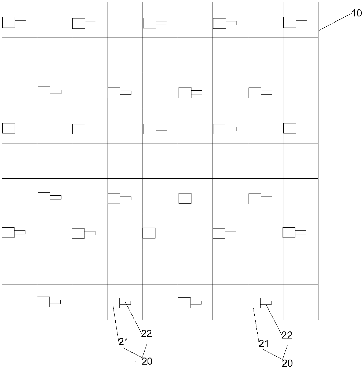
[0014] 2), hoisting reinforcement cage; such as figure 1 Shown is a structural schematic diagram of the reinforcement cage used in the present invention, and a plurality of vibrating devices 20 are arranged on the reinforcement cage 10 . Each vibrating device 20 includes a motor 21 and a vibrating rod 22 . The motor 21 drives the vibrating rod 22 to vibrate. The vibrating rod 22 protrudes from the steel cage 10 .

[0015] 3) Concrete is poured. During the pouring process, the vibrating device is used to exert force on the concrete to increase the flow of the concrete and form a wall.

[0016] The construction method of the underground diaphragm wall in the present invention exerts force on the concrete during the pouring process, enhances its...


PUM


Abstract

The invention discloses a diaphragm wall construction method. The diaphragm wall construction method includes the steps that firstly, trench forming is conducted; and secondly, reinforcement cage hoisting is conducted. The diaphragm wall construction method is characterized by further including the step that thirdly, concrete pouring is conducted, wherein concrete is stirred in the pouring processthrough vibration devices on the reinforcement cage, and wall forming is conducted. According to the diaphragm wall construction method, the concrete is helped by the vibration devices to penetrate through the reinforcement cage from the inner portion of the reinforcement cage and to flow to the portion outside the reinforcement cage, the whole reinforcement cage is wrapped in the concrete, and the risk that the reinforcement cage is exposed and corroded is prevented. Motors and vibrating bars are adopted for the vibration devices, the vibration range can be increased, more concrete can be vibrated so that liquidity can be enhanced, and distribution is more uniform.

Description

technical field [0001] The invention relates to the construction of an underground continuous wall. Background technique [0002] The underground diaphragm wall is a foundation project. During construction, a trenching machine is used on the ground to excavate a narrow and long deep trench along the peripheral axis of the deep excavation project under the condition of mud retaining wall. After clearing the tank, hang the reinforcement cage in the tank, and then use the conduit method to pour underwater concrete to form a unit tank section. This is done section by section, and a continuous reinforced concrete wall is built underground as a water interception, anti-seepage, load-bearing, and water-retaining structure. The underground diaphragm wall is suitable for pumping stations, pools; building foundation pits; underground oil depots and warehouses; municipal pipe trenches and culverts; shafts of shield tunneling and other projects; various deep foundations and pile found...

Claims


Application Information

Patent Timeline
Patent Type & Authority Applications(China)
IPC IPC(8): E02F3/47E02D5/18
CPCE02D5/187E02F3/475
Inventor 梁艳文
Owner SHANGHAI YUANFANG GROUNDWORK ENG
Why Eureka
Eureka Blog
Learn More