Fluid Universal Compliant and Force Sensing Hands for Robots

A technology of sensing palm and pressure sensor, applied in the field of fluid universal compliance and force sensing palm for robots, can solve the problems of high stiffness buffer, damping effect, poor spring working state and weak buffer capacity, etc. Matching problems, increasing adaptability, reducing system cost effects

Inactive Publication Date: 2021-03-30
HARBIN INST OF TECH
View PDF11 Cites 0 Cited by
  • Summary
  • Abstract
  • Description
  • Claims
  • Application Information

AI Technical Summary

Problems solved by technology

[0002] The robot end effector is a mechanism that directly interacts with the environment. In the traditional mechanism design, it has a large rigidity and almost no controllable buffer at the end, so it has poor interaction with the environment, especially in legged robots. During running, the foot end collides with the ground at high speed. The traditional foot end uses a rubber pad with a very weak cushioning capacity, which is far from sufficient in terms of cushioning and compliance; using springs or elastic materials for cushioning, the damping effect and the working state of the spring are extremely poor, which may easily cause spring damage. Failure, there is an uncontrollable spring link, and the stiffness and damping of the foot end are uncontrollable; the hydraulic cylinder and servo valve buffer system are complex systems, and the ground is not universally compliant, and it is difficult to meet the requirements for lightweight and miniaturized terminals. The multi-dimensional force still uses a six-dimensional force sensor, which further increases the complexity and cost of the system, and it is difficult to implement complex algorithms for variable stiffness control and damping control

Method used


Image

  • Fluid Universal Compliant and Force Sensing Hands for Robots
  • Fluid Universal Compliant and Force Sensing Hands for Robots
  • Fluid Universal Compliant and Force Sensing Hands for Robots

Examples


Embodiment 1

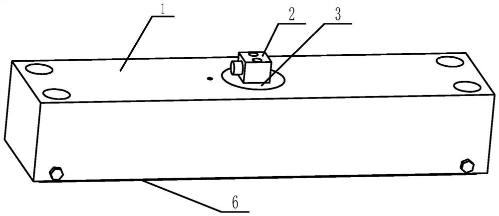
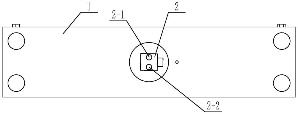
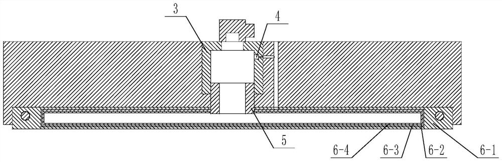
[0018] Such as figure 1 , 2 As shown, a fluid universal compliance and force sensing palm for a robot includes a housing 1, a solenoid valve 2, a control chamber 3, a pressure sensor 4, a temperature sensor, and a sensing palm unit 6. The housing 1 It is rectangular, and a control cavity 3 is installed in the housing 1, and a sensing palm unit 6 is installed on the bottom surface of the housing 1. The upper end of the control cavity 3 is connected with the solenoid valve 2, and the lower end of the control cavity 3 passes through the The pipe 5 is connected to the sensing palm unit 6, and the pressure sensor 4 is located on the inner wall of the control chamber 3. The sensing palm unit 6 includes an outer rubber layer 6-1, a strain sensing layer 6-2, and a metal reinforcement layer 6-3 and the inner rubber layer 6-4, the metal reinforcement layer 6-3 and the strain sensing layer 6-2 are bonded together, and sandwiched between the inner rubber layer 6-4 and the outer rubber la...

Embodiment 2

[0020] Such as Figure 4-5 As shown, a fluid universal compliance and force sensing palm for a robot includes a housing 1, a solenoid valve 2, a control chamber 3, a pressure sensor 4, a temperature sensor, and a sensing palm unit 6. The housing 1 It is a hollow cylinder, and a control chamber 3 is installed in the housing 1, and a sensing palm unit 6 is installed on the side of the housing 1. The upper end of the control chamber 3 is connected with the solenoid valve 2, and the lower end of the control chamber 3 The pressure sensor 4 is located on the inner wall of the control cavity 3 through its inner pipe 5 and connected to the sensing palm unit 6. The sensing palm unit 6 includes an outer rubber layer 6-1, a strain sensing layer 6-2, and a metal reinforcement layer. 6-3 and the inner rubber layer 6-4, after the metal reinforcement layer 6-3 and the strain sensing layer 6-2 are pasted together, they are sandwiched between the inner rubber layer 6-4 and the outer rubber lay...

Embodiment 3

[0022] Such as Figure 6-7As shown, a fluid universal compliance and force sensing palm for a robot includes a solenoid valve 2, a control cavity 3, a pressure sensor 4, a temperature sensor, and a sensing palm unit 6. The sensing palm unit is spherical, The upper end of the control cavity 3 is connected to the solenoid valve 2, the lower end of the control cavity 3 is connected to the sensor palm unit 6 through the inner pipeline 5, the pressure sensor 4 is located on the inner wall of the control cavity 3, and the sensor The palm unit 6 includes an outer rubber layer 6-1, a strain sensing layer 6-2, a metal reinforcement layer 6-3 and an inner rubber layer 6-4. After the metal reinforcement layer 6-3 and the strain sensing layer 6-2 are bonded together , sandwiched between the inner rubber layer 6-4 and the outer rubber layer 6-1, the cavity of the sensing palm unit 6 is filled with a certain amount of liquid, the strain sensing layer 6-2 is equipped with a temperature senso...


PUM


Abstract

The invention discloses a liquid universal compliant and force sensing palm for a robot. The liquid universal compliant and force sensing palm for the robot comprises a solenoid valve, a control chamber, a pressure sensor, a temperature sensor and a sensing palm unit, the upper end of the control chamber is connected with the solenoid valve, the lower end of the control chamber is connected with the sensing palm unit through an internal pipe, the pressure sensor is positioned on the inner wall of the control chamber, and the sensing palm unit comprises an outer rubber layer, a strain sensing layer, a metal reinforcing layer and an inner rubber layer. After the metal reinforcing layer and the strain sensing layer are bonded together, the sensing palm unit is sandwiched between the inner rubber layer and the outer rubber layer, and the sensing palm unit is filled with a certain amount of liquid. The liquid universal compliant and force sensing palm for the robot realizes variable dampingbuffer and variable rigidity adaptation in the interaction process, solves the impact and non-compliance problems caused by the large rigidity and undamped interaction of the traditional robot end environment interaction mechanism, and makes the interaction process non-impact and compliant.

Description

technical field [0001] The invention belongs to the technical field of industrial production, and in particular relates to a fluid universal compliance and force sensing palm for a robot. Background technique [0002] The robot end effector is a mechanism that directly interacts with the environment. In the traditional mechanism design, it has a large rigidity and almost no controllable buffer at the end, so it has poor interaction with the environment, especially in legged robots. During running, the foot end collides with the ground at high speed. The traditional foot end uses a rubber pad with a very weak cushioning capacity, which is far from sufficient in terms of cushioning and compliance; using springs or elastic materials for cushioning, the damping effect and the working state of the spring are extremely poor, which may easily cause spring damage. Failure, there is an uncontrollable spring link, and the stiffness and damping of the foot end are uncontrollable; the h...

Claims


Application Information

Patent Timeline
Patent Type & Authority Patents(China)
IPC IPC(8): B62D57/032
CPCB62D57/032
Inventor 丛大成李加启杨志东张燕燕
Owner HARBIN INST OF TECH
Why Eureka
Try Eureka