
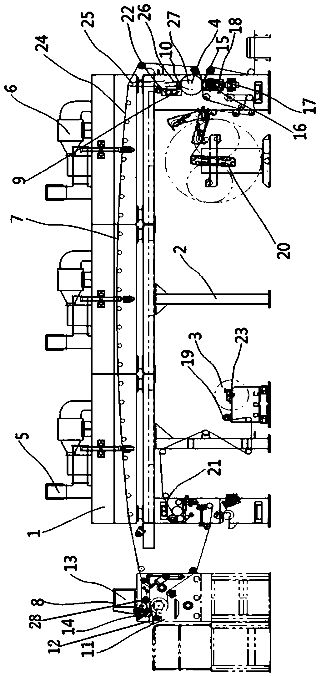
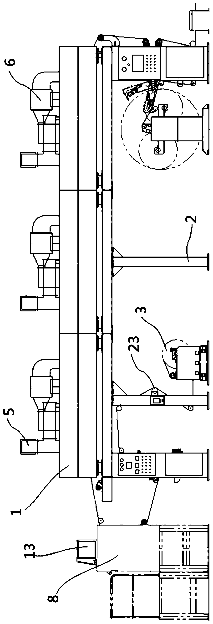
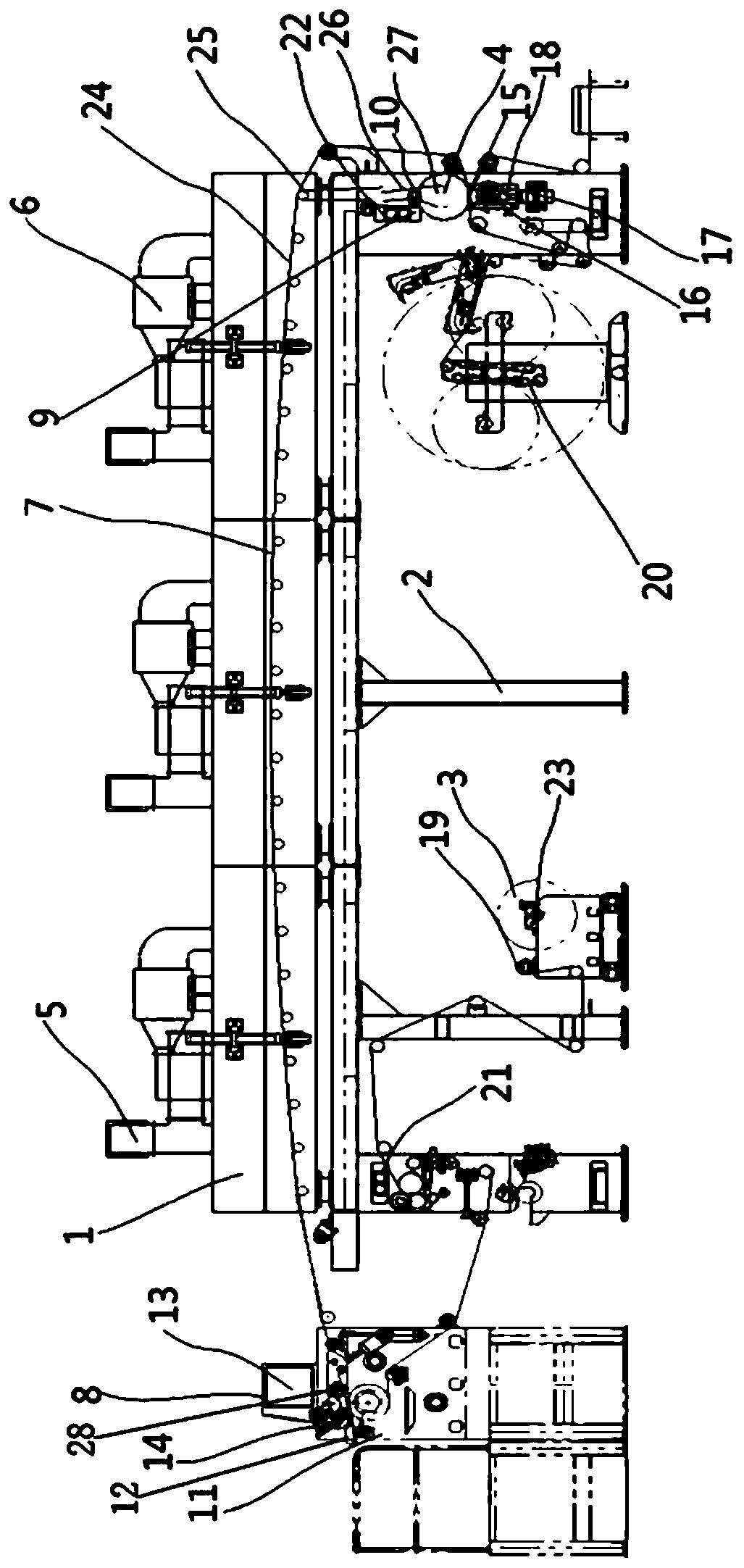
Hot stamping machine and positioning and hot stamping method thereof

A technology for hot stamping machines and casings, which is applied to printing machines, rotary printing machines, and general parts of printing machinery, etc. Waste, avoid surface fouling, and not easy to absorb dust

Pending Publication Date: 2019-07-05
广州风光新型材料科技有限公司
View PDF0 Cites 2 Cited by
  • Summary
  • Abstract
  • Description
  • Claims
  • Application Information

AI Technical Summary

Problems solved by technology

[0003] The existing hot stamping machine basically includes a frame, a feeding device, a conveying device and a receiving device. After a period of time, misplaced hot stamping occurs between the materials and the parts to be printed. The misplaced hot stamped parts cannot be reused, resulting in a great waste of materials. The post-calibration of the machine accuracy and the repurchase of materials have increased a lot of expenses for the company. At the same time, the hot stamping process requires high temperature, and the odor produced is also threatening the health of the operator. With the increase of production time, the material is in a high temperature environment for a long time, causing the material to generate static electricity due to over-drying, which is easy to absorb dust, resulting in The pattern is not beautiful enough

Method used


Image

  • Hot stamping machine and positioning and hot stamping method thereof
  • Hot stamping machine and positioning and hot stamping method thereof
  • Hot stamping machine and positioning and hot stamping method thereof

Examples


Embodiment Construction

[0041] The accompanying drawings are for illustrative purposes only, and should not be construed as limitations on this patent; in order to better illustrate this embodiment, certain components in the accompanying drawings will be omitted, enlarged or reduced, and do not represent the size of the actual product; for those skilled in the art It is understandable that some well-known structures and descriptions thereof may be omitted in the drawings.

[0042] In the description of the present invention, it should be noted that unless otherwise specified and limited, the terms "installation" and "connection" should be understood in a broad sense, for example, it can be a fixed connection, a detachable connection, or an integral Ground connection; it can be a mechanical connection or an electrical connection; it can be a direct connection or an indirect connection through an intermediary. It can be said that the internal communication of two components. Those of ordinary skill in ...


PUM


Abstract

The invention relates to the field of production and processing, in particular to a hot stamping machine and a positioning and hot stamping method thereof. The hot stamping machine comprises a machineshell, a machine frame, a material device, a hot stamping device, an air inlet, an exhaust fan, a conveying device and a detection device, wherein the air inlet and the exhaust fan are correspondingly fixed at the top end of the machine shell, the machine shell is fixed outside the machine frame, the detection device is connected with the conveying device, the conveying device is arranged in themiddle of the machine frame, the hot stamping device is arranged beside the material device, and the hot stamping device is arranged between the air inlet and the conveying device. According to the hot stamping machine and the positioning and hot stamping method thereof, the detection device is arranged, so that hot stamping dislocation caused by the offset of a material or the offset of a to-be-printed part during hot stamping of the hot stamping machine is effectively avoided, the relative positions of the material and the to-be-printed part can be adjusted in time, and then the accuracy ofthe hot stamping position and the attractiveness of a hot stamping part are ensured.

Description

technical field [0001] The invention relates to the field of production and processing, more specifically, to a hot stamping machine and a positioning hot stamping method thereof. Background technique [0002] With the development of technology, many jobs that were originally done manually have been gradually replaced by machines, which not only reduces the labor intensity of workers, but also improves production efficiency. [0003] The existing hot stamping machine basically includes a frame, a feeding device, a conveying device and a receiving device. After a period of time, the materials and the parts to be printed are misplaced and hot stamped. The misplaced hot stamped parts cannot be reused, resulting in a great waste of materials. The post-calibration of the machine accuracy and the repurchase of materials have increased a lot of expenses for the company. At the same time, the hot stamping process requires high temperature, and the odor produced is also threatening ...

Claims


Application Information

Patent Timeline
Patent Type & Authority Applications(China)
IPC IPC(8): B41F19/06B41F23/00B41F33/16B41F35/00
CPCB41F19/06B41F19/068B41F23/002B41F33/16B41F35/00
Inventor 金风光
Owner 广州风光新型材料科技有限公司
Learn More