
Vertical vibrating sand removal device

A vertical, vibrating motor technology, applied in the field of casting core sand removal devices, can solve the problems of core sand not being discharged in time, the mechanism is shaking, and the sand removal efficiency is low. Sand efficient effect

Pending Publication Date: 2019-07-05
WUXI HUAZHU MACHINERY IND CO LTD
View PDF0 Cites 2 Cited by
  • Summary
  • Abstract
  • Description
  • Claims
  • Application Information

AI Technical Summary

Problems solved by technology

The horizontal sand removal mechanism replaces the manual sand removal and improves the traditional operation, but there are still some problems: first, it is troublesome to fix the casting horizontally, not only the two ends of the casting must be clamped, but also the bottom must be fixed; two Yes, after shaking, the loose core sand in the casting cannot be discharged in time, and the sand removal efficiency is low and incomplete; third, when shaking, the entire mechanism shakes, the equipment is unstable, and there are potential safety hazards; fourth, when the mechanism shakes, The casting itself does not shake enough. If the entire mechanism shakes too much, the casting will loosen even if it is fixed.

Method used


Image

  • Vertical vibrating sand removal device
  • Vertical vibrating sand removal device
  • Vertical vibrating sand removal device

Examples


Embodiment Construction

[0021] The present invention will be further described below in combination with specific embodiments.

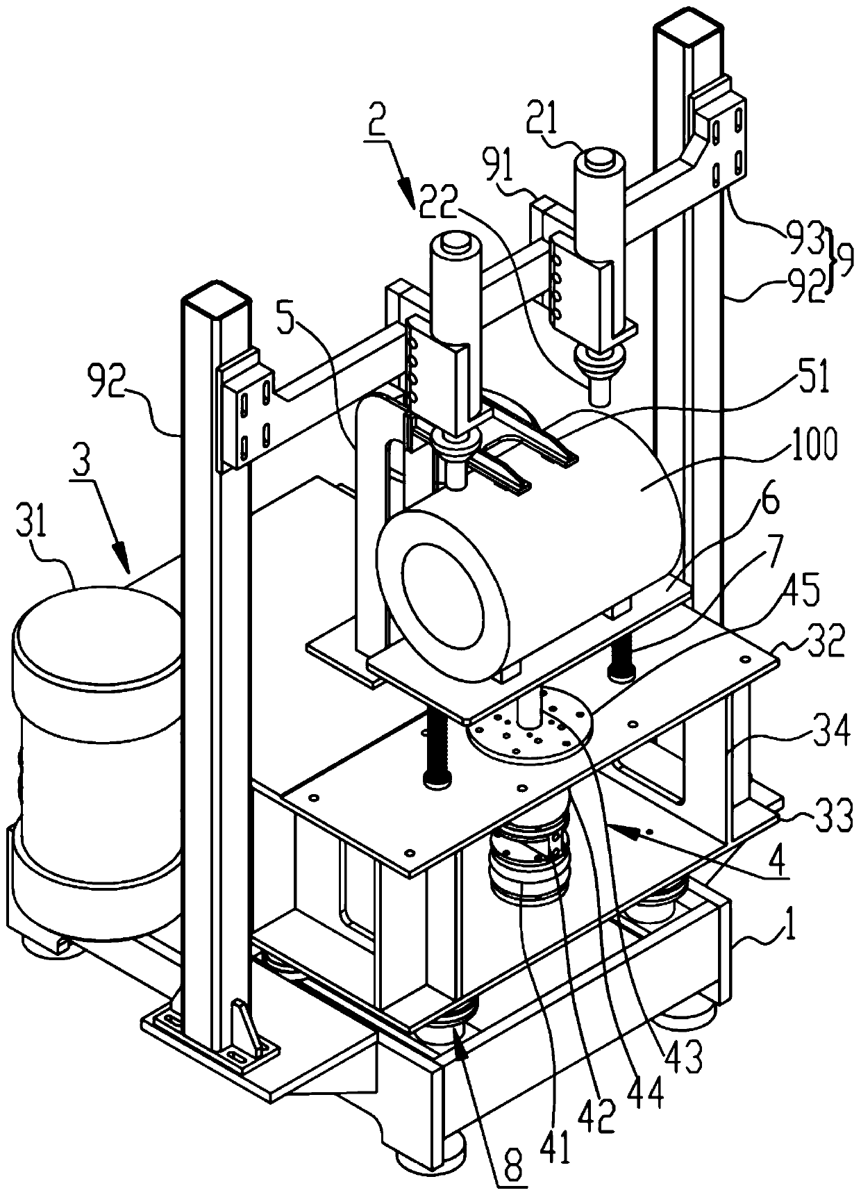
[0022] like figure 1 As shown, a vertical vibrating sand removal device according to an embodiment of the present invention includes a base 1 , a hammering mechanism 2 , a vibrating mechanism 3 , an air spring lifting mechanism 4 and an upper clamping seat 5 . The vertical vibrating sand removal device is mainly used to remove the core sand in the casting 100. The casting 100 includes the motor casing, the aluminum alloy cylinder head of the automobile engine, the supercharger, etc., and the device is mainly used in the company for removing the motor casing. sand.

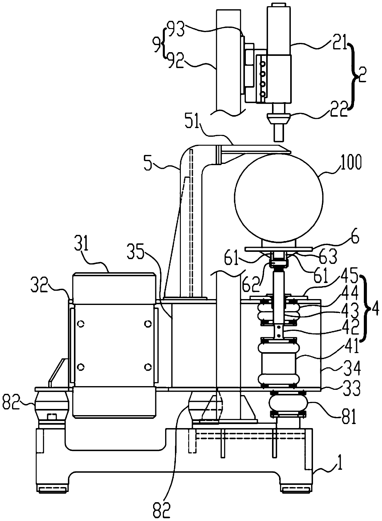
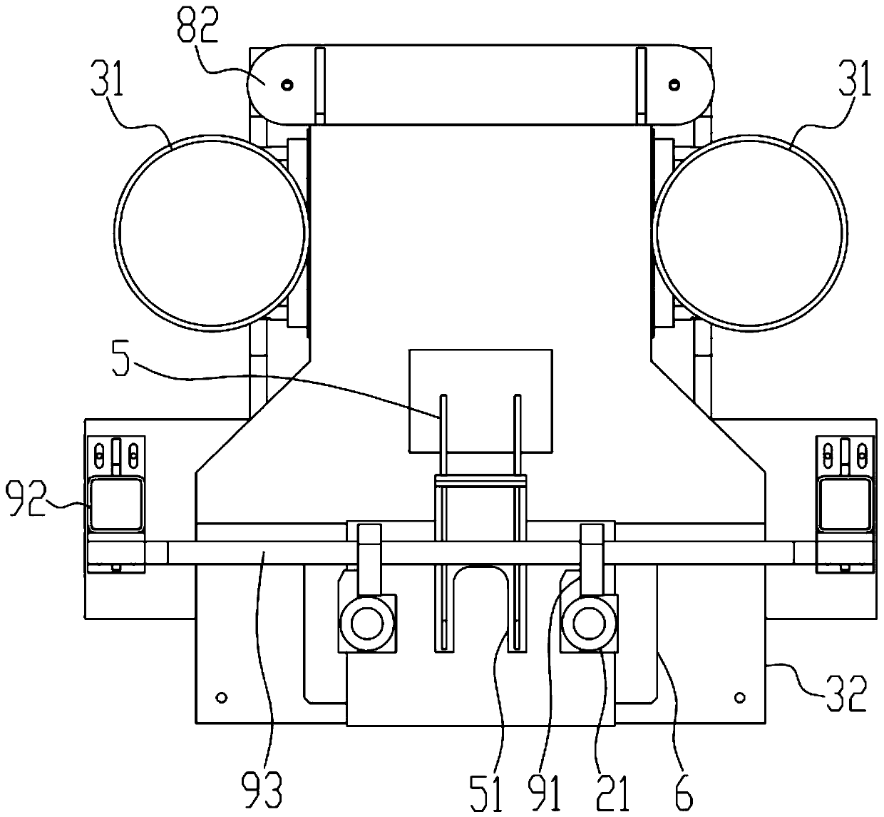
[0023] like figure 2 and 3 As shown, the vibration mechanism 3 includes a vibration motor 31 , an upper support 32 , a lower support 33 , and a plurality of vertical plates 34 connecting the upper support 32 and the lower support 33 . The upper frame 32 and the lower frame 33 overlap on the vertical project...


PUM


Abstract

The invention discloses a vertical vibrating sand removal device. The vertical vibrating sand removal device comprises a base, hammering mechanisms, a vibrating mechanism, an air spring lifting mechanism and an upper clamping seat; the vibrating mechanism comprises vibrating motors, an upper bracket, a lower bracket and vertical plates; the upper bracket is connected with the lower bracket throughthe vertical plates; the vibrating motors are fixed to the side edges of the upper bracket and the lower bracket through a side plate; the air spring lifting mechanism comprises an air spring, a guide rod, a fixed spring and a fixed plate; the air spring is installed on the lower bracket; the guide rod is arranged on the air spring, and sequentially penetrates through the fixed spring, the upperbracket and the fixed plate vertically upwards; the fixed plate is connected with the upper bracket; the upper part of the guide rod is connected with a workbench; springs are arranged between the workbench and the upper bracket; the upper clamping seat is provided with clamping arms, and is installed on the upper bracket; the lower bracket is arranged above the base; buffering assemblies are arranged between the lower bracket and the base; and the hammering mechanisms are located above the workbench. A casting can be rapidly fixed, the casting is fixed firmly, and has a free space to shake inthe vibrating process, the base is stable, sand removal is complete, and the efficiency is high.

Description

technical field [0001] The invention relates to the technical field of casting core sand removal devices, and more specifically relates to a vertical vibration sand removal device. Background technique [0002] Sand casting is a widely used casting method. For example, castings such as motor casings, aluminum alloy cylinder heads of automobile engines, and superchargers can be sand cast. After the casting is cast, the core sand in the casting needs to be cleaned. The traditional method of removing sand from castings is manual hand-held air pick, the pick head is aimed at the casting, and the impact mechanism is used to drive the pick head to strike the casting, so as to achieve the purpose of sand removal. However, there are many problems in manual sand removal, such as the removal of core sand is not clean, long-term operation of pneumatic picks seriously affects the hearing of workers, and the efficiency of core sand removal is low. [0003] Later, in order to solve the ...

Claims


Application Information

Patent Timeline
Patent Type & Authority Applications(China)
IPC IPC(8): B22D31/00
CPCB22D31/002
Inventor 赵中星李兴成
Owner WUXI HUAZHU MACHINERY IND CO LTD
Learn More