
Orthopedic external fixing support

An external fixation and orthopedic technology, applied in the field of medical devices, can solve the problems of cumbersome installation process, stiffness, and difficulty in popularizing external fixation brackets, and achieve the effects of convenient and flexible adjustment, optimal use effect, and flexible installation process

Pending Publication Date: 2019-07-05
吴旭华 +3
View PDF10 Cites 1 Cited by
  • Summary
  • Abstract
  • Description
  • Claims
  • Application Information

AI Technical Summary

Problems solved by technology

However, this method has the following disadvantages: the stress receptor is integrally installed on the frame body, which not only plays the role of stress detection, but also is a part of the support assembly, so it is necessary to install the stress receptor at the beginning of the bracket installation. The method and installation location are planned, and it is difficult to modify during or after installation
This will cause the following problems: Some patients who have already installed ordinary brackets want to install additional stress measuring instruments to understand their healing status, but this technology must remove the original fixed brackets and reinstall the brackets with stress measuring instruments. accomplish
In addition, when the stress measuring instrument cannot work normally due to installation errors or calculation errors, it is necessary to reinstall the bracket to solve the problem
It is precisely because of its rigid and cumbersome installation process that it is difficult to popularize external fixation brackets with strain gauges

Method used


Image

  • Orthopedic external fixing support
  • Orthopedic external fixing support
  • Orthopedic external fixing support

Examples


Embodiment Construction

[0020] The present invention is further elaborated below by specific embodiment:

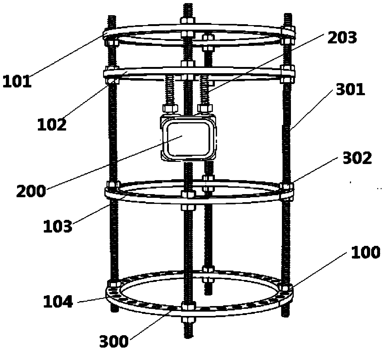
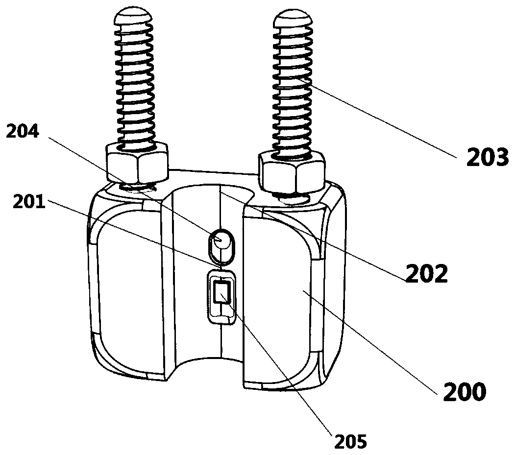
[0021] The first embodiment of the orthopedic external fixation bracket of the present invention is as follows: figure 1 with figure 2 As shown, it includes the first fixed ring 101, the second fixed ring 102, the third fixed ring 103 and the fourth fixed ring 104 which are arranged coaxially and parallelly from top to bottom. The shapes and sizes of the four fixed rings are consistent, and the four A plurality of installation holes 300 evenly distributed at specified intervals are arranged on the circumferential direction of the fixed ring, and the fixed ring 100 is fixedly connected by four screw rods 301 evenly distributed in the installation holes 300 along the circumferential direction, and the fixed ring 100 is fixed on two sides of each screw rod 301 There are vacant mounting holes 300 on each side, and the screw 301 is also provided with nuts 302 that are screwed and fixed on the upper...


PUM


Abstract

The invention provides an orthopedic external fixing support. The orthopedic external fixing support comprises a plurality of fixing rings arranged coaxially and in parallel and a plurality of supporting rods which are connected with the fixing rings. The orthopedic external fixing support is characterized by further comprising a stress measuring instrument mounted on the fixing rings, wherein thestress measuring instrument comprises a laser sensor facing the supporting rods, and the laser sensor can detect the distance between the laser sensor and the supporting rods. When the stress of thesupport is changed, the support rods can generate corresponding deformation, the distance measured by a distance sensor is changed, and an effect of measuring the stress of the support can be achievedby analyzing the relationship between the distance change and the stress. Compared with the prior art, the orthopedic external fixing support has the advantages that external connection can be conveniently carried out under the condition that the original structure of the support is not damaged, and compared with a rigid and complicated mounting process in the prior art, the mounting mode of theorthopedic external fixing support is more flexible, and a better using effect is achieved.

Description

technical field [0001] The invention relates to the field of medical instruments, in particular to an orthopedic external fixation bracket. Background technique [0002] Orthopedic external fixator is an important treatment tool and means for fixing fractures and correcting limb deformities. Commonly used external fixation brackets include ring-shaped external fixation brackets, single-arm external fixation brackets, multi-link brackets, and six-axis brackets. At present, several key issues that need to be solved clinically for external fixation brackets are how to follow up the healing of fractures in real time, when to decide to remove the external fixation brackets, whether the correction is in place, and how to better communicate with patients. Chinese patent CN101513359 discloses an external fixation bracket, which includes a pluggable left frame body and a right frame body, and a stress sensor and an intelligent controller arranged on the left frame body. The device ...

Claims


Application Information

Patent Timeline
Patent Type & Authority Applications(China)
IPC IPC(8): A61B17/62G01L1/04
CPCA61B17/62G01L1/04
Inventor 吴旭华夏庆泉容可
Owner 吴旭华
Learn More