
Composite gas discharge tube

A composite gas and discharge tube technology, applied in solid cathode components and other directions, can solve the problems of inconvenient external circuits, unsuitable use, complex protection circuits, etc., and achieve the effects of convenient external circuits, reducing product size, and improving integration.

Pending Publication Date: 2016-09-21
SHENZHEN BENCENT ELECTRONICS CO LTD
View PDF7 Cites 0 Cited by
  • Summary
  • Abstract
  • Description
  • Claims
  • Application Information

AI Technical Summary

Problems solved by technology

However, connecting other electronic components in series in the protection circuit makes the protection circuit complicated and the external circuit is inconvenient; it also increases the occupied area of ​​the protection circuit, which is not suitable for use in some occasions.

Method used


Image

  • Composite gas discharge tube
  • Composite gas discharge tube
  • Composite gas discharge tube

Examples


Embodiment Construction

[0018] In the following, the present invention will be further described by using the following embodiments in conjunction with the accompanying drawings. It should be noted in advance that the insulating tube body referred to in the present invention is glass tube, porcelain tube or other insulating tube body suitable for composite gas discharge tube; the composite gas discharge tube referred to in the present invention includes triode and multi-electrode tube. For simplicity of description, a triode is used as an example for illustration.

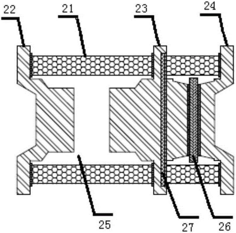
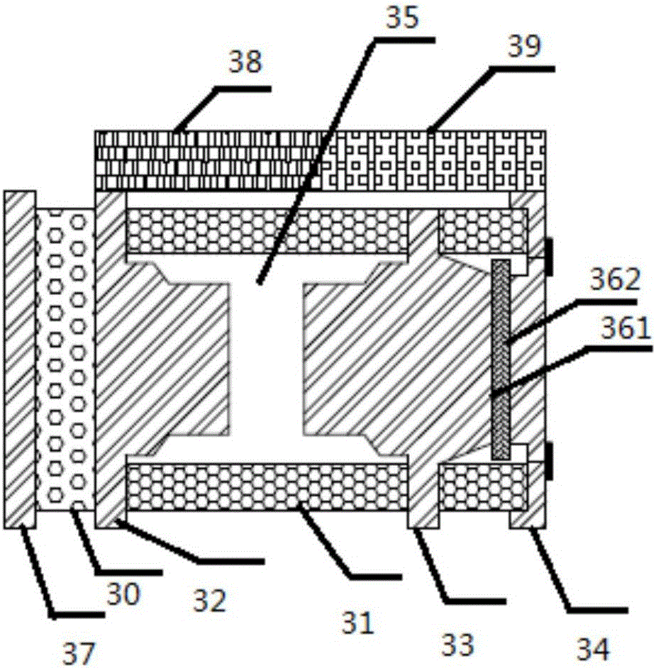
[0019] see figure 1 , figure 1 It is a schematic diagram of the appearance of the composite gas discharge tube provided in Embodiment 1 of the present invention. Such as figure 1 As shown, the composite gas discharge tube of this embodiment includes: an insulating tube body 11, a first electrode 12, an intermediate electrode 13 and a second electrode 14, and the first electrode 12, the intermediate electrode 13 are sealed and connected...


PUM


Abstract

The present invention provides a composite gas discharge tube which comprises an insulating tube body and at least three electrodes which comprise a first electrode, an intermediate electrode and a second electrode. The first electrode, the intermediate electrode and the insulating tube body are connected in a sealed way to form a discharge inner chamber filled with gas. The surface of the intermediate electrode facing the second electrode is provided with a chip component or a chip component group. The chip component or chip component group comprises two conductive surfaces which are a first conductive surface and a second conductive surface. The first conductive surface is electrically connected to the intermediate electrode, and the second conductive surface is electrically connected to the second electrode. According to the composite gas discharge tube, the chip component which is used with a common gas discharge tube in series is packaged in the composite gas discharge tube, the degree of integration is high, the size is small, and the external connection of a circuit is convenient.

Description

technical field [0001] The invention relates to the field of overvoltage protection products, in particular to a composite gas discharge tube. Background technique [0002] The gas discharge tube is a switch type protection device, usually used as an overvoltage protection device. The gas discharge tube commonly used at present is made of an insulating tube body and electrodes sealed at both ends, and the inner cavity is filled with inert gas. When the voltage across the electrodes of the gas discharge tube exceeds the breakdown voltage of the gas, a gap discharge will be caused, and the gas discharge tube will quickly change from a high-resistance state to a low-resistance state, forming a conduction, thereby protecting other devices connected in parallel with it. . However, due to the performance limitation of the gas discharge tube, in the practical application of some protective circuits, the use of the gas discharge tube alone often fails to meet the requirements, and...

Claims


Application Information

Patent Timeline
Patent Type & Authority Applications(China)
IPC IPC(8): H01J17/34
CPCH01J17/34
Inventor 付猛
Owner SHENZHEN BENCENT ELECTRONICS CO LTD
Learn More