DNA molecular logic gate based on DNA ribozyme
A technology of DNA molecules and logic gates, applied in the field of DNA molecular logic gates, can solve the problems of lack of connection information flow links and difficulties, and achieve the effect of wide application prospects.
- Summary
- Abstract
- Description
- Claims
- Application Information
AI Technical Summary
Problems solved by technology
Method used
Image


Examples
Embodiment 1
[0085] Example 1 The Basic YES Gate of DNA Molecules Based on DNAzymes
[0086] Such as figure 1 As shown, a DNA molecular logic gate based on DNAzyme, including: input signal, DNA logic calculation unit and output signal,
[0087] The input signal includes: DNA catalytic chain H1;
[0088] The DNA logic calculation unit includes: A chain, DNA complex B (Complex B, including B / B1 / B2) and a signal substrate; the B1 chain and the B2 chain are not connected; the A chain and the B chain are hybridized and connected Composition of DNAzyme-1 with endonuclease function;
[0089] The DNAzyme-1 can recognize a specific sequence in the signal substrate, and catalyze the cleaving of the signal substrate to release the signal;
[0090] The DNA catalytic chain H1 can be combined with the cohesive end of the B chain to undergo a strand displacement reaction;
[0091] On the B chain, there is a binding site of the A chain at the hybridization position between the B chain and the B1 chain...
Embodiment 2
[0100] Example 2 DNA molecule cascade YES gate based on DNAzyme
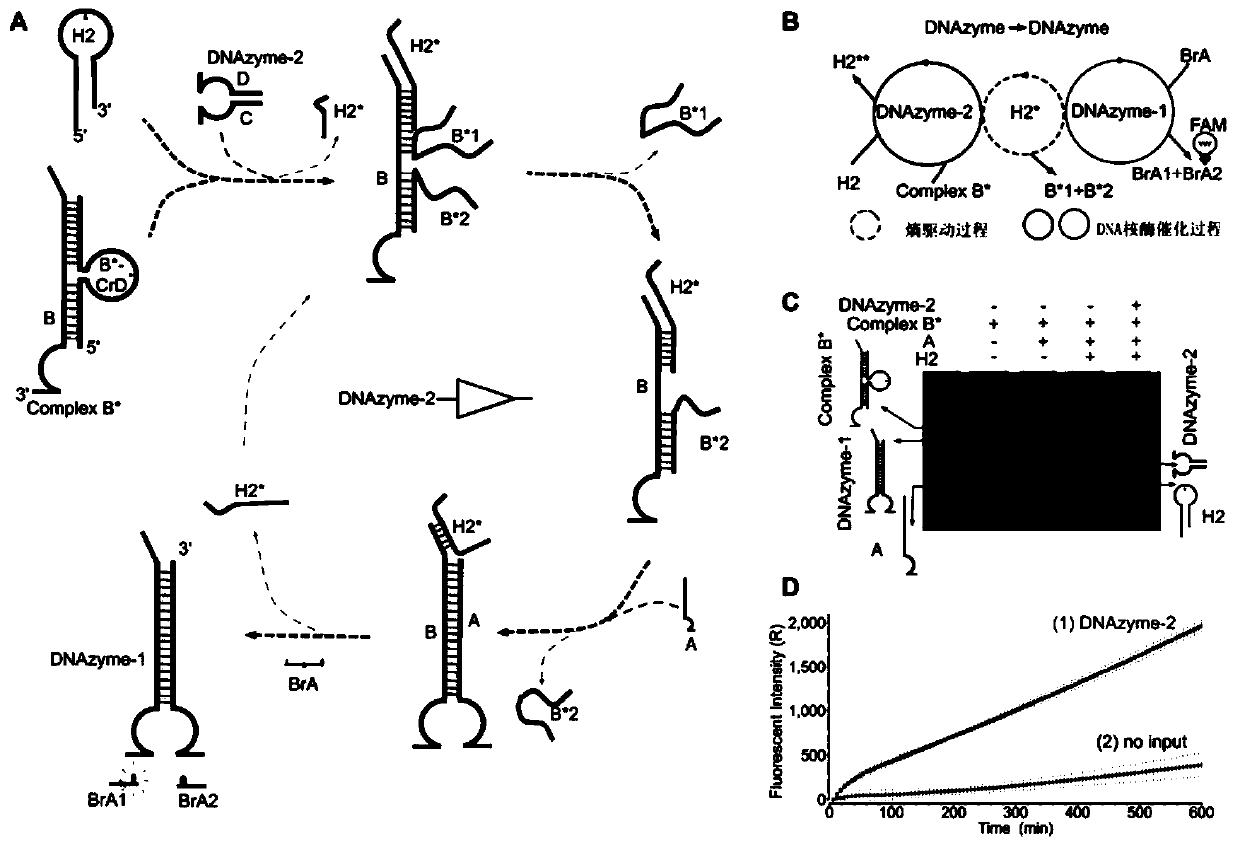
[0101] In order to study the feasibility of constructing a DNAzyme-based molecular logic circuit, the cascaded YES gate in this example was developed and constructed. The circuit is designed to be triggered by DNAzyme input and generate another DNAzyme. The specific DNA strand sequences involved in this example are shown in Table 1.
[0102] Such as image 3 As shown, in this system, the DNAzyme DNAzyme-2 (such as image 3 , DNAzyme-2 is composed of the hybridization of the D-strand and C-strand sequences in Table 1) was designed as an input signal to trigger the cascade YES gate and generate the DNAzyme DNAzyme-1, thereby causing an increase in fluorescence intensity.
[0103] The DNA molecular cascade YES gate includes: an input signal, a DNA logic calculation unit and an output signal, and the input signal includes: DNAzyme-2;
[0104] The DNA logic calculation unit includes: DNA complex B* (Complex B*, in...
Embodiment 3
[0108] Cascade two-layer YES gate of embodiment 3 ribozyme regulation
[0109] In order to test the scalability of the molecular logic circuit based on DNAzyme regulation, a cascaded two-layer YES gate is established in this embodiment. It mainly generates DNAzyme-2a through the regulation of DNAzyme-3 (DNAzyme-3 is formed by the hybridization of D1 chain and C1 chain sequence in Table 1), and then generates DNAzyme-1 through the regulation of DNAzyme-2a. The specific DNA strand sequences involved in this example are shown in Table 1.
[0110] Such as Figure 5 As shown, DNAzyme-3 is designed as the input signal of the YES gate of the first layer; for the computing unit of the first layer, the DNA logic computing unit includes the DNA complex D(D' chain and D*-ErF chain, wherein the chain The position of the loop on D*-ErF sets the cleavage site, and D*1 and D*2 are connected by the sequence of the loop position), the catalytic chain H4 and the C' chain.
[0111] Then, thro...
PUM
 Abstract
Description
Claims
Application Information
 - R&D
- Intellectual Property
- Life Sciences
- Materials
- Tech Scout
- Unparalleled Data Quality
- Higher Quality Content
- 60% Fewer Hallucinations
Browse by: Latest US Patents, China's latest patents, Technical Efficacy Thesaurus, Application Domain, Technology Topic, Popular Technical Reports.
© 2025 PatSnap. All rights reserved.Legal|Privacy policy|Modern Slavery Act Transparency Statement|Sitemap|About US| Contact US: help@patsnap.com