


Quick Research
Generate reliable direction feasibility study reports for your R&D in just a few steps.

Technical Q&A
Discover and master advanced knowledge NOW. Basics, ideas, possibilities, all at once.

Find Solutions
As an expert in R&D theories, this can generate solutions to your technical problems instantly.

Evaluate Feasibility
Analyze your overall solution with one click, know your potential R&D risks in advance.

Monitor Landscape
Get weekly tech updates, stay abreast of the latest tech innovations and key insights.
Automatic control gear shifting device based on linear motor
A linear motor and shifting device technology, applied in transmission control, mechanical equipment, components with teeth, etc., can solve problems such as difficulty in adjusting the speed of gear control, influence of processing and installation accuracy, and low repeatability of positioning accuracy. , to achieve the effect of simple structure, fast response speed and convenient operation
- Summary
- Abstract
- Description
- Claims
- Application Information
AI Technical Summary
Problems solved by technology
Method used
Image

Examples
Embodiment 1
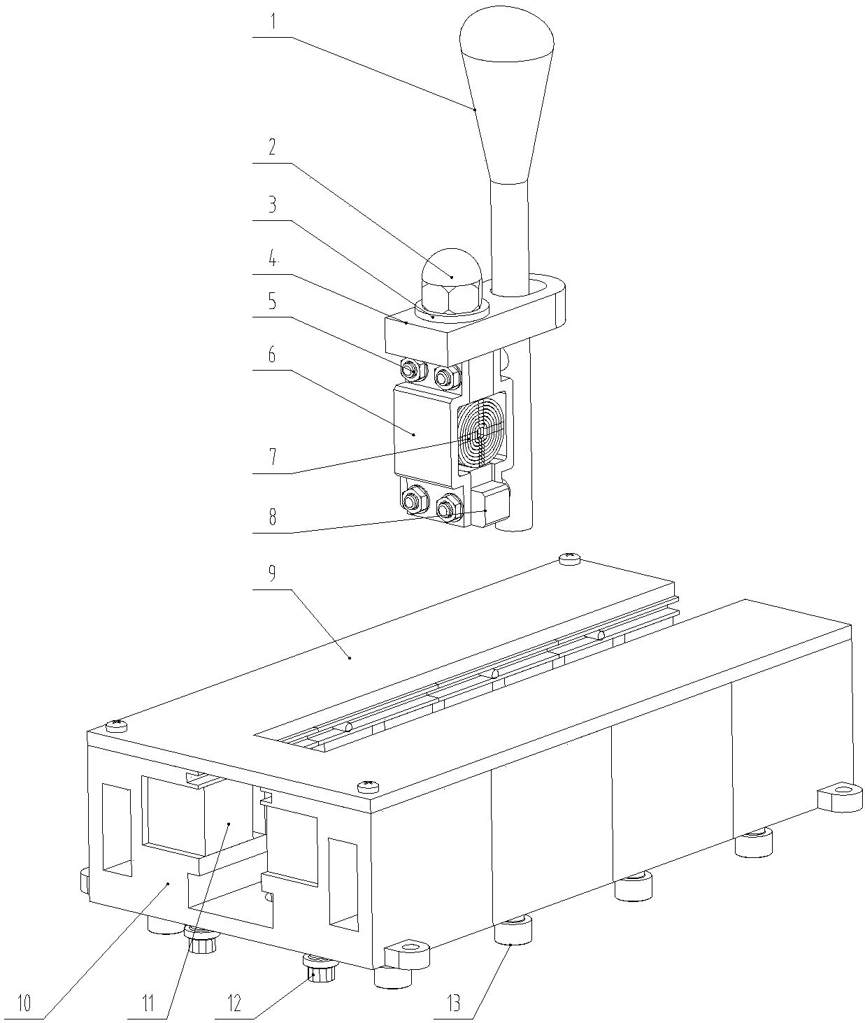
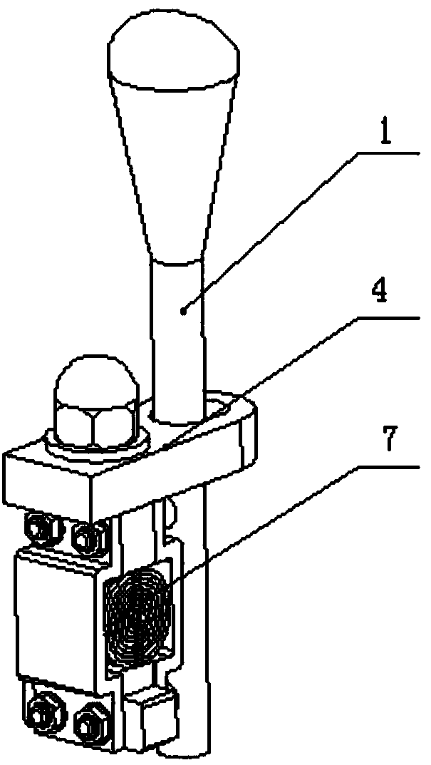
[0032] This embodiment provides an automatic control gear shifting device based on a linear motor, including a linear gear shift mechanism 14; The subassembly, the moving subassembly slides in the stator assembly, driving the stopper rod 1 to move;
[0033] The stator assembly includes: a control circuit board 9, a stator base 10, a permanent magnet 11, and a movable limit sensor 16; the control circuit board 9 is placed on the stator base 10, and the stator base 10 is provided with a guide groove, so The above-described guide grooves include guide grooves I18, guide grooves II19 and guide grooves III20 arranged from top to bottom, and guide groove II19 is placed between guide grooves I18 and guide grooves III20; permanent magnets 11 are symmetrically distributed in guide grooves II19, which can be The movement limit sensor 16 is placed in the guide groove I18, the magnetic pole direction of the permanent magnet 11 is perpendicular to the direction of the guide groove II19, an...
Embodiment 2
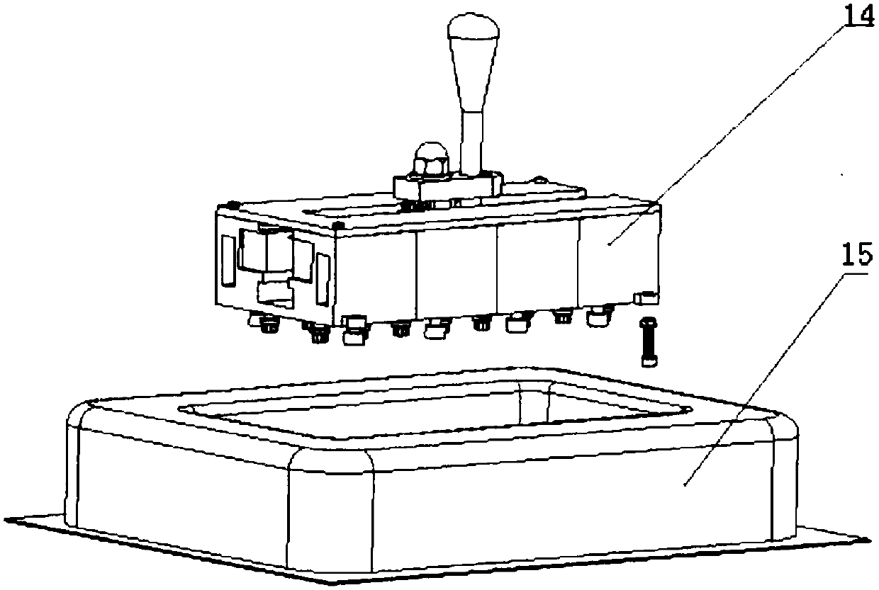
[0039] The linear shift mechanism 14 described in embodiment 1 is installed and fixed in the hollow armrest box 15, and the shift dust cover is removed earlier before installation, and the figure 2 A plurality of fixing bolts shown fix the base of the linear shift mechanism 14 in the center control armrest box 15 inside.
[0040] The permanent magnet 11 is fixed on the stator base 10. The permanent magnet is a 20mmx20mmx20mm square magnetic pole. The direction of the magnetic pole is perpendicular to the direction of the guide groove II19. Fixed, easy to move and adjust the position of the permanent magnet. The mover slider 8 of the mover assembly and the stator assembly cooperates with the guide groove III20, and lubricating oil is applied in the guide groove III20, so that the mover slider 8 can slide freely in the guide groove III20;
[0041] The mover coil 7 can move linearly under the magnetic field after being energized, thereby driving the blocking rod 1 to move back ...
PUM
 Abstract
Description
Claims
Application Information
 - R&D Engineer
- R&D Manager
- IP Professional
- Industry Leading Data Capabilities
- Powerful AI technology
- Patent DNA Extraction
Browse by: Latest US Patents, China's latest patents, Technical Efficacy Thesaurus, Application Domain, Technology Topic, Popular Technical Reports.
© 2024 PatSnap. All rights reserved.Legal|Privacy policy|Modern Slavery Act Transparency Statement|Sitemap|About US| Contact US: help@patsnap.com