
Smart cable, smart cable preparation method and smart cable safety state detection method

A technology of intelligent cable and safe state, which is applied in geotechnical structure and large concrete structure, intelligent cable preparation, intelligent cable safety state detection, bridge structure, intelligent cable field, and can solve problems such as layout difficulties and achieve seamless Effects of installation error, low insertion loss, and easy layout

Pending Publication Date: 2019-07-02
武汉地震工程研究院有限公司 +1
View PDF0 Cites 2 Cited by
  • Summary
  • Abstract
  • Description
  • Claims
  • Application Information

AI Technical Summary

Problems solved by technology

In this method, multi-core optical fibers are compounded in fiber-reinforced plastic bars to make fiber-reinforced optical fiber bars. Since fiber-reinforced plastic bars are easy to process and form, and are compatible with the coating layer of multi-core optical fibers, fiber-reinforced optical fiber bars It combines the good mechanical properties and corrosion resistance of fiber-reinforced plastic ribs and the sensing characteristics of multi-core optical fibers, completely overcoming the shortcomings of fiber optic sensors that are fragile and difficult to deploy

Method used


Image

  • Smart cable, smart cable preparation method and smart cable safety state detection method
  • Smart cable, smart cable preparation method and smart cable safety state detection method
  • Smart cable, smart cable preparation method and smart cable safety state detection method

Examples


Embodiment Construction

[0040] The specific embodiments of the present invention will be described in detail below in conjunction with the technical solutions and accompanying drawings.

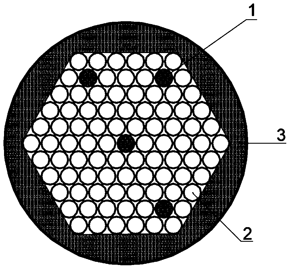
[0041] figure 1 It is a schematic cross-sectional view of an embodiment of the present invention, including a fiber-reinforced optical fiber tie bar 1, a tie bar 2 (the tie bar 2 adopts steel wire or steel strand in this embodiment), and a sheath 3. The fiber-reinforced optical fiber tie bars 1 and the tie bars 2 are equally long and thickly blanked. When the smart cable is processed and formed, the fiber-reinforced optical fiber tie bar 1 replaces at least one tie bar 2 in the cable, and the outer cover of the cable is covered with a sheath 3. The end of the dragline has an anchor head (not shown).

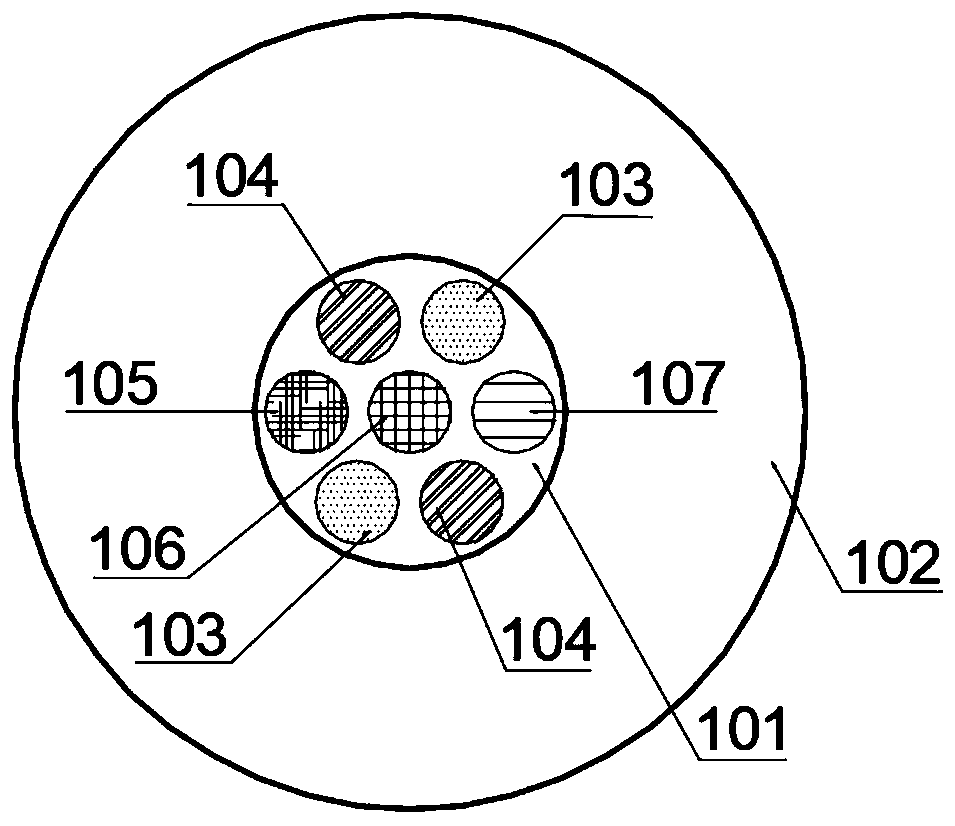
[0042] combine figure 2, the multi-core optical fiber 101 is placed in the center of the fiber-reinforced plastic rib 102 along the length direction of the rib, and the fiber-reinforced optical fiber tie bar 1 is ma...


PUM


Abstract

The invention discloses a smart cable, a smart cable preparation method and a smart cable safety state detection method. The smart cable comprises a jacket and tie bars arranged in the jacket, whereinat least one tie bar in the jacket is replaced by a fiber enhanced optical fiber tie bar; the fiber enhanced optical fiber tie bar comprises a multi-core optical fiber and a fiber enhanced plastic rib wrapping the periphery of the multi-core optical fiber; the multi-core optical fiber is placed in the center of the rib in the length direction of the fiber plastic enhanced rib; the fiber enhancedoptical fiber tie bar is made through a pulling-extruding molding process; during machining and molding of the smart cable, at least one tie bar in the cable is replaced by the fiber enhanced opticalfiber tie bar; the cable is coated with the jacket, and an anchor gear is mounted to obtain the smart cable based on multi-core fiber sensing. The multi-core optical fiber is combined with the cable organically, so that the cable has the characteristics of high modulus, high durability, creep resistance and the like, and the stress change, bending change, temperature change and vibration change ofan in-service cable can be measured accurately in a distribution manner.

Description

technical field [0001] The invention belongs to the field of civil engineering structures, and relates to a civil structure safety monitoring and structural material technology, in particular to an intelligent cable, an intelligent cable preparation method and an intelligent cable safety state detection method, which are applicable to bridge structures and geotechnical structures and large concrete structures. Background technique [0002] The cable is the core component of many engineering structures. Due to the influence of the environment, the current cable is prone to rust, corrosion, and fatigue damage. The actual service time is much lower than the design service time, and there are great safety hazards. Therefore, realizing on-line monitoring, safety assessment and life estimation of in-service cables is a very important and promising work. At present, the cable monitoring methods widely used in engineering include: 1) Arranging sensors outside the cable, commonly us...

Claims


Application Information

Patent Timeline
Patent Type & Authority Applications(China)
IPC IPC(8): E01D19/16E04B1/00E04B1/34E02D17/20G01D21/02
CPCE01D19/16E04B1/00E04B1/34E02D17/20G01D21/02
Inventor 冯谦白石席晓卿蔡思佳欧进萍
Owner 武汉地震工程研究院有限公司
Learn More