
Particle agglomeration device for low temperature plasma charging ultrasonic atomization liquid drops

A low-temperature plasma, atomized droplet technology, applied in solid separation, separation methods, electrostatic effect separation, etc., can solve the problems of pipeline deposition, difficult to stabilize and effectively condense particulate matter, blockage, etc., and achieve low cost and large application. and the effect of promoting value and avoiding damage

Active Publication Date: 2019-06-28
XI AN JIAOTONG UNIV
View PDF11 Cites 4 Cited by
  • Summary
  • Abstract
  • Description
  • Claims
  • Application Information

AI Technical Summary

Problems solved by technology

The device is mainly used for dust removal in coal mines. The purpose is to reduce the dust concentration of the gas below the limit concentration of dust explosion. However, the mixed flow of ultrasonic atomized liquid droplets and high-concentration dust-containing gas will easily cause pipeline deposition and blockage, so long-term operation is difficult. Stable and effective condensation of particulate matter

Method used


Image

  • Particle agglomeration device for low temperature plasma charging ultrasonic atomization liquid drops
  • Particle agglomeration device for low temperature plasma charging ultrasonic atomization liquid drops
  • Particle agglomeration device for low temperature plasma charging ultrasonic atomization liquid drops

Examples


Embodiment Construction

[0028] The present invention will be further described in detail below in conjunction with specific embodiments, which are explanations of the present invention rather than limitations.

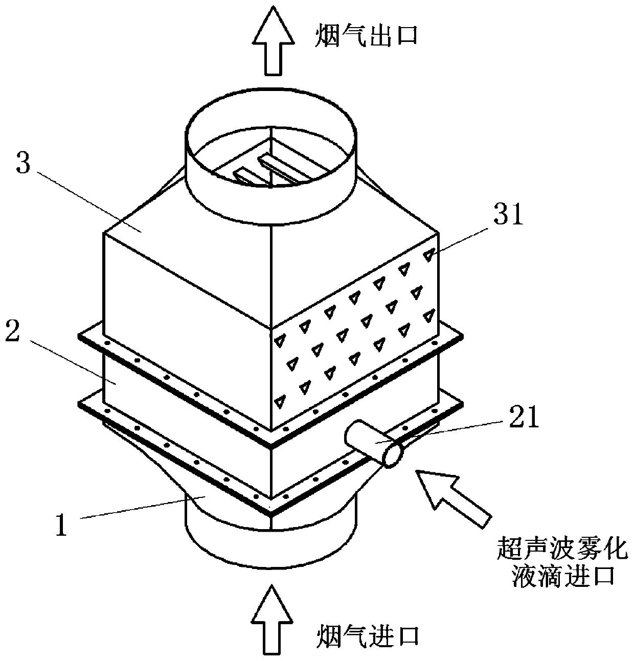
[0029] The invention relates to a low-temperature plasma charged particle agglomeration device for ultrasonically atomized liquid droplets, which is arranged in sequence along the flue gas flow with an inlet gradual expansion section 1 , an atomization charging section 2 and a turbulent flow agglomeration section 3 . The atomization charging section 2 includes an atomization charging tube 21 and an anti-wear tile 22, which can be used for low-temperature plasma charging of the atomized liquid droplets generated by ultrasonic atomization, and the charging voltage is 5-20kV. The particle size of the charged atomized droplets is 1-20 μm; the atomized charging tube has a tree-like branched tubular structure, and the charging area is sequentially composed of a high-voltage electrode 215, a barrier ...


PUM


Abstract

The invention relates to a particle agglomeration device for low temperature plasma charging ultrasonic atomization liquid drops. The particle agglomeration device comprises an inlet gradual-expandingsection, an atomization charging section and a turbulence flow agglomeration section which are distributed along the flow direction of smoke, wherein the atomization charging section comprises an atomization charging pipe; the atomization charging pipe comprises a middle linkage pipe and a plurality of branched pipes, the middle linkage pipe is provided with an ultrasonic atomization liquid dropinlet, and the branched pipes are arranged on two sides of the middle linkage pipe in a communication manner; each branched pipe comprises a charging shell, a through-flow end cap and a fixed end cover, the charging shell is inserted into the middle linkage pipe, the through-flow end cap is arranged at a connecting end of the charging shell, and the fixed end cover is arranged at a free end of thecharging shell; a plurality of charging liquid drop nozzles are arranged above the charging shell along the flow direction of the smoke, a blocking medium is coaxially arranged in the charging shell,two ends of the blocking medium are respectively fixed on the through-flow end cap and the fixed end cover, and a high-voltage electrode inserted through a fixed end cover is arranged in the blockingmedium; the charging shell is connected with a ground wire so as to form a discharging high-voltage loop; a gap for the communication of the atomization liquid drops is formed between the blocking medium and the charging shell; and the turbulence flow agglomeration section comprises a shell and an eddying element.

Description

technical field [0001] The invention relates to the technical field of particulate matter emission control in the coal-burning industry, in particular to a particle agglomeration device for low-temperature plasma charged ultrasonically atomized liquid droplets. Background technique [0002] Fine particulate matter PM emitted by coal-burning industry 2.5 (Particulate matter with a kinetic diameter less than 2.5 μm) has an important impact on the atmospheric environment and human health. Traditional industrial dust removal equipment (such as electrostatic precipitator, bag filter, wet electrostatic precipitator, etc.) has a penetration window in the range of 0.1-2 μm due to different dust removal mechanisms for particles of different particle sizes. Low efficiency results in massive emissions of fine particles. Adding a particle coagulation pretreatment device based on the traditional dust removal technology is a new technical means that can effectively solve the difficulty ...

Claims


Application Information

Patent Timeline
Patent Type & Authority Applications(China)
IPC IPC(8): B01D51/02B03C3/017
Inventor 谭厚章刘鹤欣杨富鑫李正鸿冯鹏
Owner XI AN JIAOTONG UNIV
Learn More