Eureka AIR delivers breakthrough ideas for toughest innovation challenges, trusted by R&D personnel around the world.

A dust removal waste gas treatment device

A technology of waste gas treatment device and gas outlet head, applied in separation method, sedimentation tank, separation of dispersed particles, etc., can solve the problems of insufficient absorption of absorbing liquid and waste gas, and the adsorption efficiency needs to be improved, so as to improve the adsorption effect and accelerate the precipitation. Effect

Active Publication Date: 2021-06-08
江西中南环保设备有限公司
View PDF5 Cites 0 Cited by
  • Summary
  • Abstract
  • Description
  • Claims
  • Application Information

AI Technical Summary

Problems solved by technology

[0003] Adsorption tower is a commonly used waste gas treatment equipment. Traditional adsorption towers simply set atomizing nozzles in the tank. The absorption liquid and waste gas are not fully absorbed, and the adsorption efficiency needs to be improved.

Method used


Image

  • A dust removal waste gas treatment device
  • A dust removal waste gas treatment device
  • A dust removal waste gas treatment device

Examples


Embodiment 1

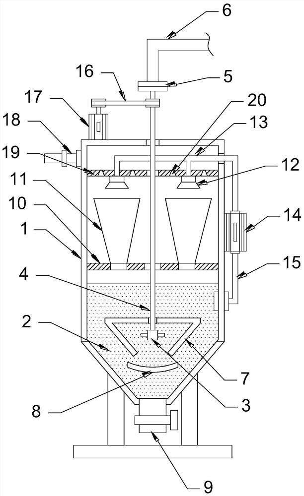
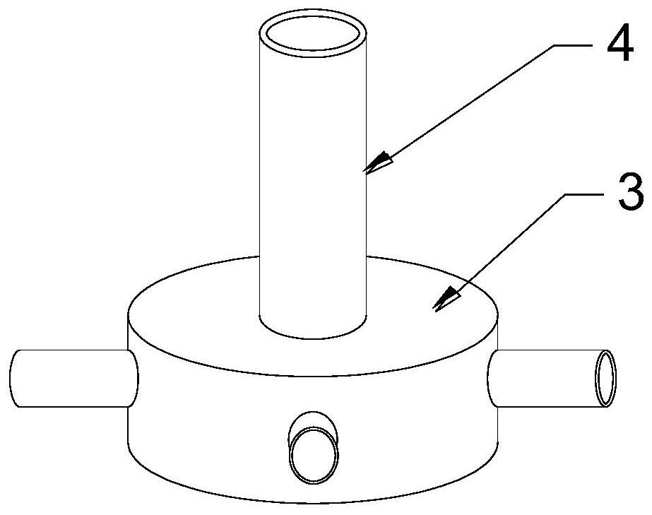
[0021] see Figure 1~4 , in an embodiment of the present invention, a dust removal waste gas treatment device includes a tank body 1, an atomizing nozzle 12 and a lift pump 14; the lower part of the tank body 1 is provided with a sedimentation chamber 2, which is a conical chamber, and 2 is filled with absorption liquid; the precipitation chamber 2 is provided with an air outlet head 3, and the air outlet head 3 is provided with a gas outlet branch pipe distributed in a circle, so that the exhaust gas is evenly dispersed in the absorption liquid, and the absorption efficiency of harmful substances is improved; the air outlet The upper end of the head 3 is communicated with a central pipe 4 , the central pipe 4 extends to the top of the tank body 1 and communicates with an air intake pipe 6 through the rotary joint 5 , and exhaust gas enters the central pipe 4 from the air intake pipe 6 .

[0022] Described settling chamber 2 is provided with stirring bar 7, and stirring bar 7 ...

Embodiment 2

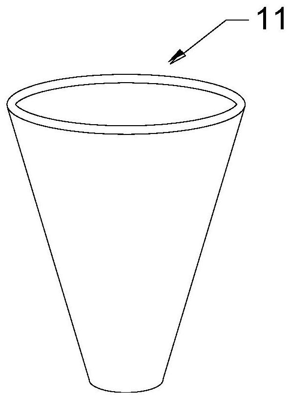
[0025] The difference between this embodiment and Embodiment 1 is that a first partition 10 is provided above the settling chamber 2, and the first partition 10 is nested with ventilators 11 distributed in a circle, and the ventilators 11 are conical cylinders. The opening diameter of the upper end of the ventilation cylinder 11 is larger than the diameter of the opening of the lower end of the ventilation cylinder 11; the ventilation cylinder 11 passes through the first partition 10 and communicates with the sedimentation chamber 2; the waste gas flows upward from the ventilation cylinder 11 after being purified by the absorption liquid; the ventilation cylinder 11 An atomizing nozzle 12 is arranged on the top, and the absorption liquid sprayed by the atomizing nozzle 12 meets the exhaust gas rising in the ventilator 11, so that the exhaust gas and the atomizing liquid are fully contacted, and the absorption effect of harmful substances in the exhaust gas is further improved; t...


PUM


Abstract

The invention discloses a dust removal waste gas treatment device, which comprises a tank body and an atomizing nozzle; a sedimentation chamber is arranged at the lower part of the tank body, and an air outlet head is arranged in the sedimentation chamber; a first partition is arranged above the sedimentation chamber, and a second Circumferentially distributed ventilators are nested on a partition, and atomizing nozzles are arranged above the ventilators. In the present invention, a rotating stirring rod is provided in the sedimentation chamber, so that the absorption liquid forms a swirling flow, which accelerates the sedimentation of the suspended matter, and prevents the sediment from being raised by the swirling flow through the shielding plate; The ventilator makes the absorption liquid collide with the exhaust gas head-on, improving the adsorption effect of the atomized liquid.

Description

technical field [0001] The invention relates to the field of waste gas treatment, in particular to a dust removal waste gas treatment device. Background technique [0002] Exhaust gas purification mainly refers to the work of treating industrial waste gas such as dust particles, flue gas smoke, odorous gas, and toxic and harmful gases generated in industrial places. Common waste gas purification includes factory smoke and dust waste gas purification, workshop dust waste gas purification, organic waste gas purification, waste gas odor purification, acid-base waste gas purification, chemical waste gas purification, etc. The exhaust gas emitted by industrial production often has harmful effects on the environment and human health. Before it is discharged into the atmosphere, purification measures should be taken to make it meet the requirements of the exhaust gas emission standard. This process is called exhaust gas purification. Commonly used exhaust gas purification methods ...

Claims


Application Information

Patent Timeline
Patent Type & Authority Patents(China)
IPC IPC(8): B01D47/02B01D47/06B01D53/18B01D21/28B01D21/02
Inventor 谭美妹香志光
Owner 江西中南环保设备有限公司
Why Eureka
Eureka Blog
Learn More