Method and apparatus for flexible circuit cable attachment

A flexible circuit and cable connection technology, which is applied in the direction of electrical connection of printed components, assembly of printed circuits and circuits with electrical components

Active Publication Date: 2019-06-25
JABLIN INC
View PDF6 Cites 0 Cited by
  • Summary
  • Abstract
  • Description
  • Claims
  • Application Information

AI Technical Summary

Problems solved by technology

[0006] In summary, there are many challenges in connecting overlappin

Method used


Image

  • Method and apparatus for flexible circuit cable attachment
  • Method and apparatus for flexible circuit cable attachment
  • Method and apparatus for flexible circuit cable attachment

Examples


Embodiment Construction

[0042] It should be appreciated that the drawings and description of the embodiments of the method and apparatus for flexible circuit cable connections have been simplified to illustrate elements that are relevant to a clear understanding, while many other elements of a typical vehicle system have been eliminated for the sake of clarity. Those of ordinary skill in the art can recognize that other elements and / or steps are desirable and / or required in implementing the present invention. However, since these elements and steps are well known in the art, and because they do not facilitate a better understanding of the present invention, a discussion of these elements and steps is not provided here.

[0043] Non-limiting embodiments described herein relate to methods and apparatus for flexible circuit cable connections. The method and apparatus for flex circuit cabling can be modified for various applications and uses while remaining within the spirit and scope of the claims. The e...


PUM


Abstract

A method and apparatus for multiple flexible circuit cable attachment is described herein. Gold bumps are bonded on interconnection pads of a substrate to create a columnar structure and solder or conductive epoxy is dispensed on the flexible cable circuit. The substrate and flexible cable circuit are aligned and pressed together using force or placement of a weight on either the substrate or flexible cable circuit. Appropriate heat is applied to reflow the solder or cure the epoxy. The solder wets to the substrate pads, assisted by the gold bumps, and have reduced bridging risk due to the columnar structure. A nonconductive underfill epoxy is applied to increase mechanical strength.

Description

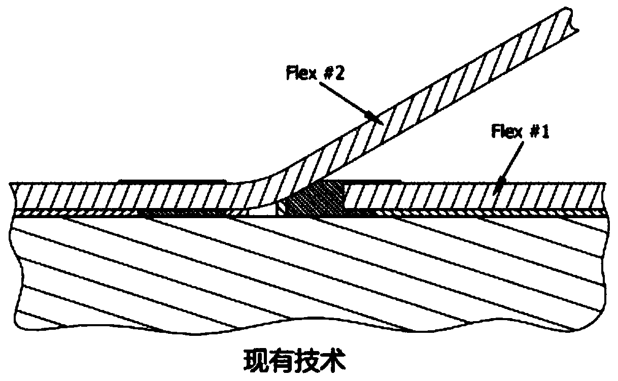
technical field [0001] The present invention relates generally to flexible circuit cables, and more particularly to the attachment of flexible circuit cables to substrates. Background technique [0002] Flexible circuit cables are widely used for chip-to-printed circuit board (PCB), chip-to-substrate, optical subassembly-to-PCB, and PCB-to-PCB interconnections. They provide high-density signal routing capabilities in a limited space and in a flexible manner. However, previous methods for connecting flex circuit cables suffer from various disadvantages. [0003] For example, direct soldering of a single flex circuit cable connection or multiple flex circuit cable connections is possible or preferred when the flex circuit cables do not overlap. However, in the case of overlapping flex circuit cables, the thermal reflow of the solder will affect the chips or flex circuit cables already attached to the substrate. For example, if figure 1 As shown, when attempting to attach f...

Claims


Application Information

Patent Timeline
IPC IPC(8): H05K3/34H05K1/11
CPCH05K3/3494H05K3/321H05K3/363H05K3/361H05K3/4015H05K1/111H05K1/117H05K13/0015H05K2203/049H05K2203/166B23K20/025B23K20/233B23K2101/42B23K2103/08B23K20/007B23K35/0222B23K35/3013Y02P70/50H01L24/80H01L21/84Y02P70/62B32B37/06B23K20/24
Inventor W·王M·A·特德曼M·P·桑托斯R·K·本茨H·李G·方
Owner JABLIN INC
Why Eureka
Try Eureka