Enhanced Coreless Induction Furnace Stirring

a coreless induction furnace and stirring technology, applied in induction heating, induction current sources, electric/magnetic/electromagnetic heating, etc., can solve the problems of increasing the risk of bridging, more difficult to draw in smaller charged pieces, etc., to enhance the stirring improve the stirring control of electrically conductive materials, and maintain the homogeneity of metallurgy and melt temperature.

Inactive Publication Date: 2018-06-21
AJAX MAGNETHERMIC CORP
View PDF0 Cites 0 Cited by
  • Summary
  • Abstract
  • Description
  • Claims
  • Application Information

AI Technical Summary

Benefits of technology

[0013]The present invention is directed to a system that provides improved stirring control of electrically conductive material via induction heating. In one aspect of the invention, there is provided a coil enhanced stirring system wherein power from the induction coil is applied to only a portion of the cavity of the crucible or ladle or other type of container that contains the conductive material (e.g., power applied to only top portion of the cavity of the container, power supplied to only the bottom portion of cavity of the container). Such a stirring arrangement is a departure from prior art stirring arrangements wherein power from the induction coils is applied to the complete portion of the longitudinal length of the cavity of the container that contains the molten metal. In one non-limiting embodiment, there is provide an induction coil that is powered from a single-phase AC source and which extends only a portion of the longitudinal length of the cavity of the container that contains the electrically conductive material. For example, if 100% of the height or longitudinal length of the cavity of the container is filled with electrically conductive material, the induction coil that is powered by a power source (e.g., AC source) only encircles or partially encircles no more than 90% of the height or longitudinal length of the cavity of the container that is filled with electrically conductive material (e.g., 5-90% of the total height or longitudinal length of the cavity of the container that is filled with electrically conductive material, and all values and ranges therebetween). In one specific non-limiting arrangement, the induction coil only encircles or partially encircles no more than 70% of the height or longitudinal length of the cavity of the container that is filled with electrically conductive material. In another specific non-limiting arrangement, the induction coil only encircles or partially encircles no more than 60% of the height or longitudinal length of the cavity of the container that is filled with electrically conductive material. In another specific non-limiting arrangement, the induction cloil only encircles or partially encircles no more than 50% of the height or longitudinal length of the cavity of the container that is filled with electrically conductive material. In another specific non-limiting arrangement, the induction coil only encircles or partially encircles less than 50% of the height or longitudinal length of the cavity of the container that is filled with electrically conductive material. In another specific non-limiting arrangement, the induction coil only encircles or partially encircles no more than 45% of the height or longitudinal length of the cavity of the container that is filled with electrically conductive material. In another specific non-limiting arrangement, the induction coil only encircles or partially encircles no more than 40% of the height or longitudinal length of the cavity of the container that is filled with electrically conductive material. The stirring arrangement in accordance with the present invention has been found to enhance the stirring of the electrically conductive material. Molten metal stirring during the melting process as well as during process holding periods is a desirable feature in coreless induction furnace systems. Good stirring helps to maintain homogeneity in metallurgy and temperature of the melt. Good stirring also helps to maximize yield on alloy additions while operating at low power for an extended period of time. Stirring can be used to reduce the risk of bridging of charge materials over the top of the molten metal as the charged materials are added to the molten material. The enhanced stirring system for coreless induction furnaces in accordance with the present invention provides these stirring features and advantages.

Problems solved by technology

As a result of the formation of the meniscus and the reduction in molten metal velocity at the surface of the melt, it becomes more difficult to draw in smaller charged pieces in the stirred mixture, and also increases the risk of bridging, especially when adding charged pieces near the end of the melting of the electrically conductive material.

Method used


Image

  • Enhanced Coreless Induction Furnace Stirring
  • Enhanced Coreless Induction Furnace Stirring
  • Enhanced Coreless Induction Furnace Stirring

Examples


Embodiment Construction

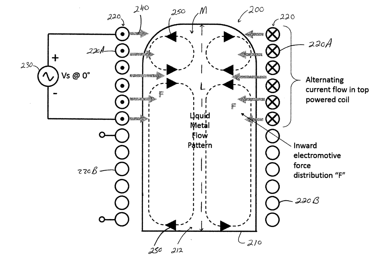
[0041]Referring now in greater detail to the drawings, wherein the showings are for the purpose of illustrating various embodiments of the invention only, and not for the purpose of limiting the invention, the present invention is directed to an apparatus and a method for enhanced stirring of melted electrically conductive material in an induction furnace. Non-limiting embodiments of the invention are illustrated in FIGS. 7-12. The apparatus and method in accordance with the present invention provides improved stirring control of electrically conductive material via induction heating. The electromotive force F that is produced by a powered induction coil located about the perimeter of a container (e.g., crucible, ladle, etc.) of the induction furnace is only applied to a portion of the longitudinal length L of the cavity of the container that contains the conductive material. Such a stirring arrangement for use in an induction furnace is novel to the art. The portion of the longitud...


PUM


Abstract

A multi-section coil enhanced stirring system wherein only one of the coils is powered from a single-phase AC source to enhance the stirring of the metal.

Description

[0001]The present invention claims priority on U.S. Application Ser. No. 62 / 434,546 filed Dec. 15, 2016, which is fully incorporated therein by reference.[0002]The present invention is directed to a coil enhanced stirring system wherein only a portion of a perimeter of an electrically conductive material to be melted is caused to be stirred by induction coils, more particularly to a coil enhanced stirring system wherein only a portion of a perimeter of an electrically conductive material to be melted is caused to be stirred by induction coils and the induction coils are powered from a single-phase AC source, still more particularly to a coil enhanced stirring system wherein only a top or bottom portion of a perimeter of an electrically conductive material to be melted is caused to be stirred by induction coils and the induction coils are powered from a single-phase AC source, yet more particularly to a multi-section coil enhanced stirring system wherein only a top or bottom portion ...

Claims


Application Information

Patent Timeline
Patent Type & Authority Applications(United States)
IPC IPC(8): H05B6/36H05B6/06H05B6/04
CPCH05B6/367H05B6/067H05B6/04H05B2213/02H05B6/06H05B6/34
Inventor LAZOR, DAVE
Owner AJAX MAGNETHERMIC CORP
Why Eureka
Try Eureka