Novel clamping bus duct

A busway and a new type of technology, applied in the direction of fully enclosed busbar devices, can solve the problems of low connection efficiency, complexity, inconvenient installation and maintenance of the busway, and achieve the effects of easy installation and disassembly, enhanced connection strength, and simplified connection methods.

Pending Publication Date: 2019-06-25
镇江市美盛母线有限公司
View PDF0 Cites 0 Cited by
  • Summary
  • Abstract
  • Description
  • Claims
  • Application Information

AI Technical Summary

Problems solved by technology

[0003] The connection methods in the existing bus duct often adopt screw fastening or welding, etc., the connection efficiency is low, and the gap is inevitable after the connection is completed, resulting in low protection ability of the bus duct, and at the same time, the inside of the bus duct is damaged. The installation and maintenance of the
[0004] However, the existing busway clamp connection methods are often more complicated, and the strength and stability of the connection are not ideal

Method used


Image

  • Novel clamping bus duct
  • Novel clamping bus duct

Examples


Embodiment Construction

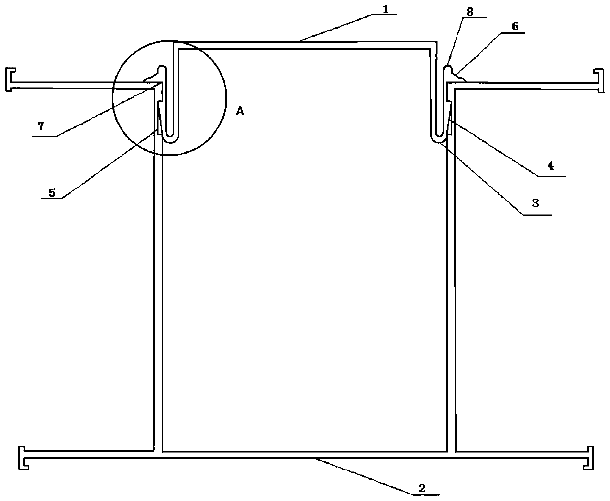
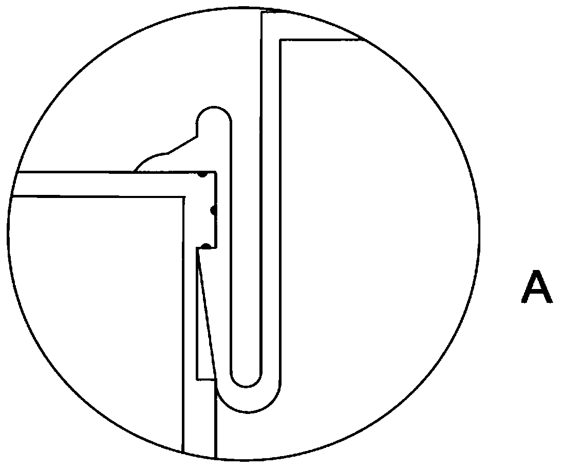
[0015] Such as figure 1 As shown, a new snap-fit ​​bus duct includes a bus bar and a bus duct housing, the bus bar is fixed in the bus duct housing, and the bus duct housing includes upper and lower cover plates and connecting The side plate between the two cover plates, the lower cover plate 2 and the side plates are made of aluminum alloy profiles with integral structure, the upper inner wall of the side plate is provided with a card slot 5, and the upper cover plate 1 Both ends of the U-shaped cantilever 3 are connected, and the outer surface of the U-shaped cantilever 3 protrudes with a block 4, and the block 4 is inserted into the slot 5; the top of the U-shaped cantilever 3 extends horizontally to both sides to form a The pressing arm 6, the upper surface of the pressing arm 6 and the block is formed with a concave notch matching the top end of the side plate, and the top end of the side plate is embedded in the concave notch. The lower part of the clamping block 4 is i...


PUM


Abstract

The invention discloses a novel clamping bus duct. The bus duct comprises a bus bar and a bus duct shell, and the bus bar is fixed in the bus duct shell. The bus duct shell comprises an upper side plate, a lower side plate and a side plate which is connected between the upper and lower side plates. The lower cover plate and the two side plates are made of aluminum alloy sections of an integral structure, and clamping grooves are formed in the inner walls of the upper portions of the side plates. U-shaped cantilevers are connected to the two ends of the upper cover plate, and clamping blocks extend out of the outer side faces of the U-shaped cantilevers in a protruding mode. The clamping blocks are clamped into the clamping grooves. The top ends of the U-shaped cantilevers horizontally extend towards the two sides to form pressing arms, and concave notches matched with the top ends of the side plates are formed in the upper surfaces of the pressing arms and the upper surfaces of the clamping blocks. The top ends of the side plates are embedded into the concave notches. By adopting the clamping mode that the clamping blocks are matched with the clamping grooves, other connection modes such as threaded connection, clamping and pasting are avoided, the connection mode between the bottom plate and the cover plate can be simplified, and the mounting and dismounting are facilitated.

Description

technical field [0001] The invention relates to a novel clamping bus duct. Background technique [0002] With the rapid development of the economy, high-rise buildings and dense industrial parks are increasing rapidly, and the design of the supporting power supply system is becoming more and more important. As a new type of power transmission and distribution equipment in the power supply system, busway The reliability of insulation, strong corrosion resistance and excellent protection against fire will gradually replace traditional cable wiring. [0003] The connection methods in the existing bus duct often adopt screw fastening or welding, etc., the connection efficiency is low, and the gap is inevitable after the connection is completed, resulting in low protection ability of the bus duct, and at the same time, the inside of the bus duct is damaged. It is very inconvenient for installation and maintenance. [0004] However, the existing clamping connection methods of bu...

Claims


Application Information

Patent Timeline
Patent Type & Authority Applications(China)
IPC IPC(8): H02G5/06
Inventor 张金荣
Owner 镇江市美盛母线有限公司
Why Eureka
Try Eureka