
Formation method of multi-stage capacitor battery

A technology of capacitor battery and formation method, applied in electrochemical generators, circuits, electrical components, etc., can solve the problems of poor power performance, short cycle life, large leakage current, etc., to improve density uniformity, prolong battery life, Reduce the effect of self-discharge

Active Publication Date: 2020-09-08
无锡凯帕德瑞科技有限公司
View PDF3 Cites 0 Cited by
  • Summary
  • Abstract
  • Description
  • Claims
  • Application Information

AI Technical Summary

Problems solved by technology

[0002] The existing mature electric double-layer supercapacitor with activated carbon as the electrode material has excellent pulse charge and discharge performance and fast charge and discharge performance, has ultra-high power density, and has a long cycle life and is relatively safe, but its energy density is relatively low. Low (generally ≤6wh / kg); lithium-ion batteries have high operating voltage and have advantages in energy density. They are currently the most promising secondary batteries. However, their power performance is poor and their low-temperature characteristics are poor (generally at -20°C The left and right discharge capacity retention rate is less than 50%), and the cycle life is short (hundreds of thousands of cycle life)
This new capacitor battery is similar to the related preparation process of lithium-ion batteries, and requires chemical formation treatment during the production process. However, the existing lithium-ion battery chemical formation process cannot meet the high-performance requirements of this new capacitor battery. After formation, the capacitor battery has high self-discharge, large leakage current, and short service life.

Method used

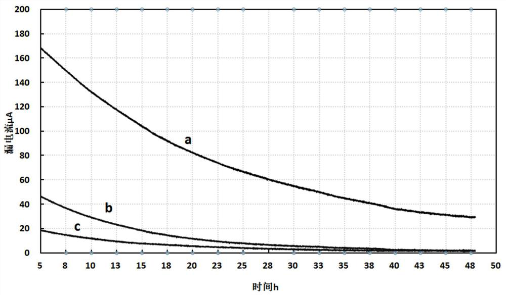
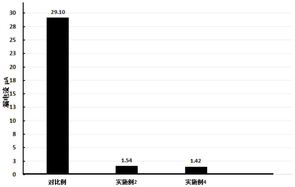
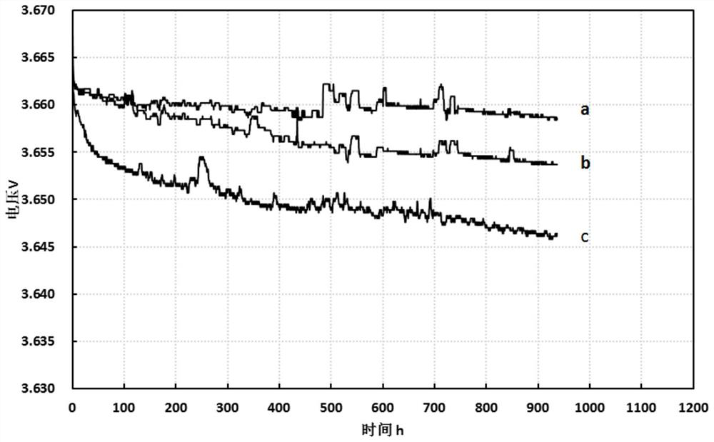

Image

  • Formation method of multi-stage capacitor battery
  • Formation method of multi-stage capacitor battery
  • Formation method of multi-stage capacitor battery

Examples


Embodiment 1

[0030] Put the capacitor battery in an environment of 40°C and normal pressure for 22 hours, and then perform the following steps:

[0031] Step 1. Under normal temperature and pressure conditions, firstly charge the capacitor battery with a constant current of 1.6mA until the voltage of the capacitor battery is 2.9V, and then charge the capacitor battery with a constant current of 5.6mA until the voltage of the capacitor battery is 3.2V;

[0032] Step 2: Charge the capacitor battery with a constant current of 3.4mA until the voltage of the capacitor battery is 3.6V, then turn off the power and let it stand for 28 minutes;

[0033] Step 3: Charge the capacitor battery with a constant current of 9.6mA until the voltage of the capacitor battery is 4V, then charge with a constant voltage of 4V for 26 minutes, and finally turn off the power and let it stand for 23 hours.

Embodiment 2

[0035] Put the capacitor battery in an environment of 45°C and normal pressure for 24 hours, and then perform the following steps:

[0036] Step 1. Under normal temperature and pressure conditions, firstly charge the capacitor battery with a constant current of 2mA until the voltage of the capacitor battery is 3V, and then charge it with a constant current of 6mA until the voltage of the capacitor battery is 3.4V;

[0037] Step 2: Charge the battery with a constant current of 4mA until the voltage of the capacitor battery is 3.7V, then turn off the power and let it stand for 30 minutes;

[0038] Step 3: Charge the capacitor battery with a constant current of 10mA until the voltage of the capacitor battery is 4V, then charge with a constant voltage of 4V for 30min, and finally turn off the power and let it stand for 24h.

Embodiment 3

[0040] Put the capacitor battery in an environment of 50°C and normal pressure for 26 hours, and then proceed to the following steps:

[0041] Step 1. Under normal temperature and pressure conditions, first charge the capacitor battery with a constant current of 2.3mA until the voltage of the capacitor battery is 3.1V, and then charge it with a constant current of 6.4mA until the voltage of the capacitor battery is 3.5V;

[0042] Step 2: Charge the capacitor battery with a constant current of 4.2mA until the voltage of the capacitor battery is 3.8V, then turn off the power and let it stand for 33 minutes;

[0043] Step 3: Charge the capacitor battery with a constant current of 10.3mA until the voltage of the capacitor battery is 4V, then charge with a constant voltage of 4V for 40min, and finally turn off the power and let it stand for 27h.


PUM


Abstract

The invention discloses a method for forming a multi-section capacitor battery. The method comprises the following steps: step 1, under normal temperature and normal pressure conditions, firstly performing constant current charging via current I1, until the voltage of the capacitor battery is V1, and then performing constant current charging via current I2, until the voltage of the the capacitor battery is V2, wherein I1 is less than I2, and V1 is less than V2; step 2, performing constant current charging via current I3, until the voltage of the the capacitor battery is V3, and performing outage for stewing, wherein I1 is less than I3 and is less than I2, and V2 is less than V3; and step 3, performing constant current charging via current I4, until the voltage of the the capacitor batteryis V4, performing constant voltage charging via V4, and finally performing outage for stewing, wherein I2 is less than I4, V3 is less than V4, and V4 represents the rated voltage of the capacitor battery. By adoption of the method for forming the multi-section capacitor battery provided by the invention, the self-discharge of the capacitor battery can be significantly reduced, the leakage currentis reduced, and the service life of the battery is prolonged.

Description

technical field [0001] The invention relates to the field of capacitor batteries. More specifically, the present invention relates to a method for forming a multi-stage capacitor battery. Background technique [0002] The existing mature electric double layer supercapacitor with activated carbon as the electrode material has excellent pulse charge and discharge performance and fast charge and discharge performance, has ultra-high power density, and has a long cycle life and is relatively safe, but its energy density is relatively low. Low (generally ≤6wh / kg); lithium-ion batteries have high operating voltage and have advantages in energy density. They are the most promising secondary batteries at present, but their power performance is poor and their low-temperature characteristics are poor (generally at -20°C The left and right discharge capacity retention rate is less than 50%), and the cycle life is short (hundreds of thousands of cycle life). With the development of ae...

Claims


Application Information

Patent Timeline
Patent Type & Authority Patents(China)
IPC IPC(8): H01M16/00
CPCY02E60/10
Inventor 陈名柱盛琦倪杰
Owner 无锡凯帕德瑞科技有限公司
Learn More