
User-level comprehensive energy system and a key equipment steady-state modeling method and device thereof

A technology that integrates energy systems and key equipment, applied in system integration technology, information technology support systems, resources, etc., can solve the problems of low energy utilization rate, low energy utilization efficiency, low energy utilization rate, etc., to improve utilization efficiency and the effect of the reliability of the energy supply

Pending Publication Date: 2019-06-21
ELECTRIC POWER RESEARCH INSTITUTE, CHINA SOUTHERN POWER GRID CO LTD +1
View PDF4 Cites 3 Cited by
  • Summary
  • Abstract
  • Description
  • Claims
  • Application Information

AI Technical Summary

Problems solved by technology

Among them, the electric heating water heater needs to consume high-grade electric energy to supply, the energy utilization rate is relatively low, and the economy is not good; the gas water heater needs to consume natural gas to supply, the energy utilization rate is not high, and there will be environmental pollution problems; and the solar energy The heat collector will not be able to supply heat at night and in rainy days due to lack of light or weak light, that is, the solar heat collector cannot achieve stable heat supply
From the above process, it can be known that satisfying the demand of the user side through a single way will result in low energy utilization efficiency, or the problem of low reliability of energy supply.

Method used


Image

  • User-level comprehensive energy system and a key equipment steady-state modeling method and device thereof
  • User-level comprehensive energy system and a key equipment steady-state modeling method and device thereof
  • User-level comprehensive energy system and a key equipment steady-state modeling method and device thereof

Examples


Embodiment Construction

[0036] The following will clearly and completely describe the technical solutions in the embodiments of the present invention with reference to the accompanying drawings in the embodiments of the present invention. Obviously, the described embodiments are only some, not all, embodiments of the present invention. Based on the embodiments of the present invention, all other embodiments obtained by persons of ordinary skill in the art without making creative efforts belong to the protection scope of the present invention.

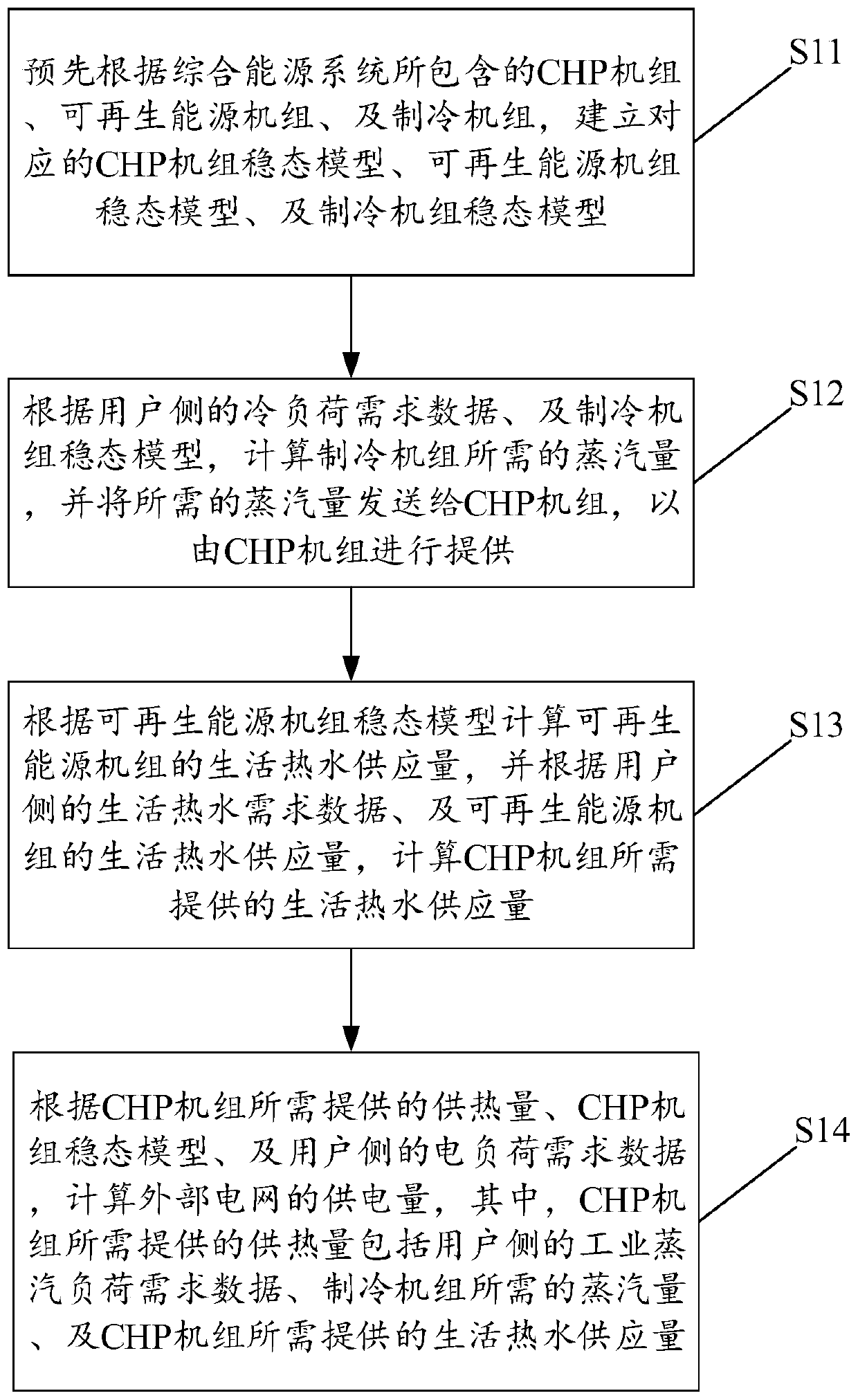
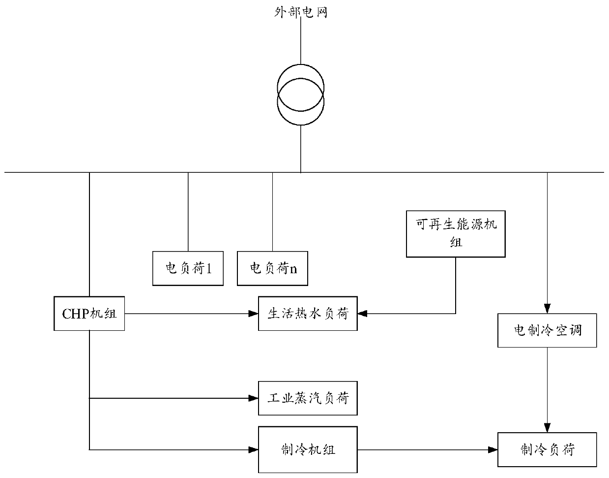
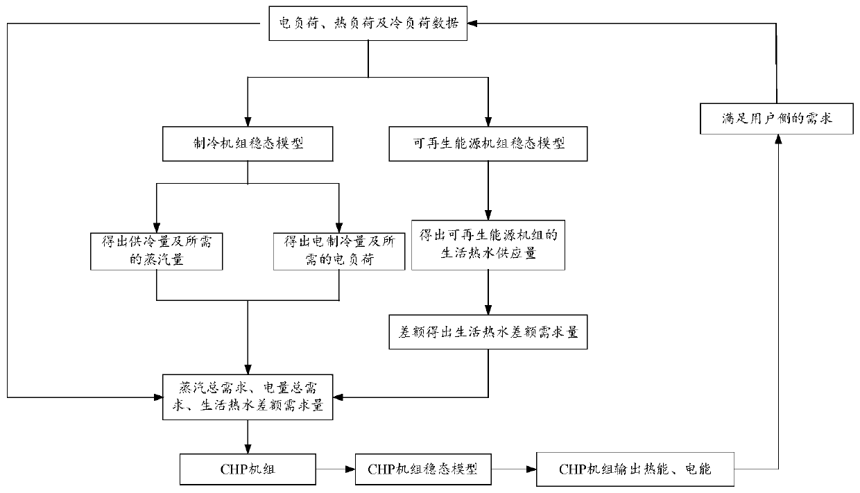
[0037] See Figure 1 to Figure 3 ,in, figure 1 It shows a flow chart of a user-level integrated energy system and its key equipment steady-state modeling method provided by an embodiment of the present invention, figure 2 It shows a schematic diagram of the composition of the user-side integrated energy system provided by the embodiment of the present invention, image 3A schematic diagram of steady-state modeling of the user-level integrated energy system ...


PUM


Abstract

The invention discloses a user-level comprehensive energy system, a key equipment steady-state modeling method and device thereof, equipment and a computer readable storage medium. The method comprises the steps that a CHP unit steady-state model, a renewable energy unit steady-state model and a refrigerating unit steady-state model are established in advance; according to the cold load demand data and the refrigerating unit steady-state model, calculating the steam amount needed by the refrigerating unit and sending the needed steam amount to the CHP unit; calculating the domestic hot water supply quantity of the renewable energy unit according to the steady-state model of the renewable energy unit, and calculating the domestic hot water supply quantity required to be provided by the CHPunit according to the domestic hot water demand data and the domestic hot water supply quantity of the renewable energy unit; And calculating the power supply quantity of the external power grid according to the heat supply quantity required to be provided by the CHP unit, the CHP unit steady-state model and the electric load demand data. According to the technical scheme disclosed by the invention, stepped utilization of energy can be realized, so that the utilization efficiency of the energy and the reliability of energy supply are improved.

Description

technical field [0001] The present invention relates to the technical field of integrated energy systems, and more specifically, to a user-level integrated energy system and its key equipment steady-state modeling method, device, equipment and computer-readable storage medium. Background technique [0002] The integrated energy system refers to the use of advanced physical information technology and innovative management models in a certain area to integrate various energy sources such as coal, oil, natural gas, electric energy, and thermal energy in a certain area to achieve coordinated planning among various heterogeneous energy subsystems. Optimal operation, collaborative management, interactive response and mutual assistance. [0003] In the existing energy supply system, the demand for electric load, heating load, and cooling load on the user side is mostly met through a single way. For example, for the domestic hot water demand on the user side, most existing energy su...

Claims


Application Information

Patent Timeline
Patent Type & Authority Applications(China)
IPC IPC(8): G06Q10/06G06Q50/06
CPCY04S10/50Y02E40/70
Inventor 郭祚刚袁智勇李鹏雷金勇马溪原周长城胡洋叶琳浩
Owner ELECTRIC POWER RESEARCH INSTITUTE, CHINA SOUTHERN POWER GRID CO LTD
Learn More