A thin-walled tube compression-bending-expansion integrated test device and method

A test device and a thin-walled tube technology, which is applied in the field of a thin-walled tube compression-bending-expansion integrated test device, can solve undisclosed problems, and achieve the effects of convenient use and maintenance, and simple structure.

Active Publication Date: 2021-07-23
SHANGHAI JIAOTONG UNIV +1
View PDF7 Cites 0 Cited by
  • Summary
  • Abstract
  • Description
  • Claims
  • Application Information

AI Technical Summary

Problems solved by technology

[0005] The above-mentioned prior art discloses that for small-sized test pieces that need to be bent with small deformation, it can be realized by using a four-point bending testing machine; for thin sheets, thin rods, etc., that need to be bent with large deformation, it can be realized by designing tooling Or it can be realized by combining tooling with a testing machine, but the technology for continuous flattening and bending of workpieces with complex geometrical sections and large scales, and recording process data has not yet been disclosed

Method used


Image

  • A thin-walled tube compression-bending-expansion integrated test device and method
  • A thin-walled tube compression-bending-expansion integrated test device and method
  • A thin-walled tube compression-bending-expansion integrated test device and method

Examples


Embodiment 1

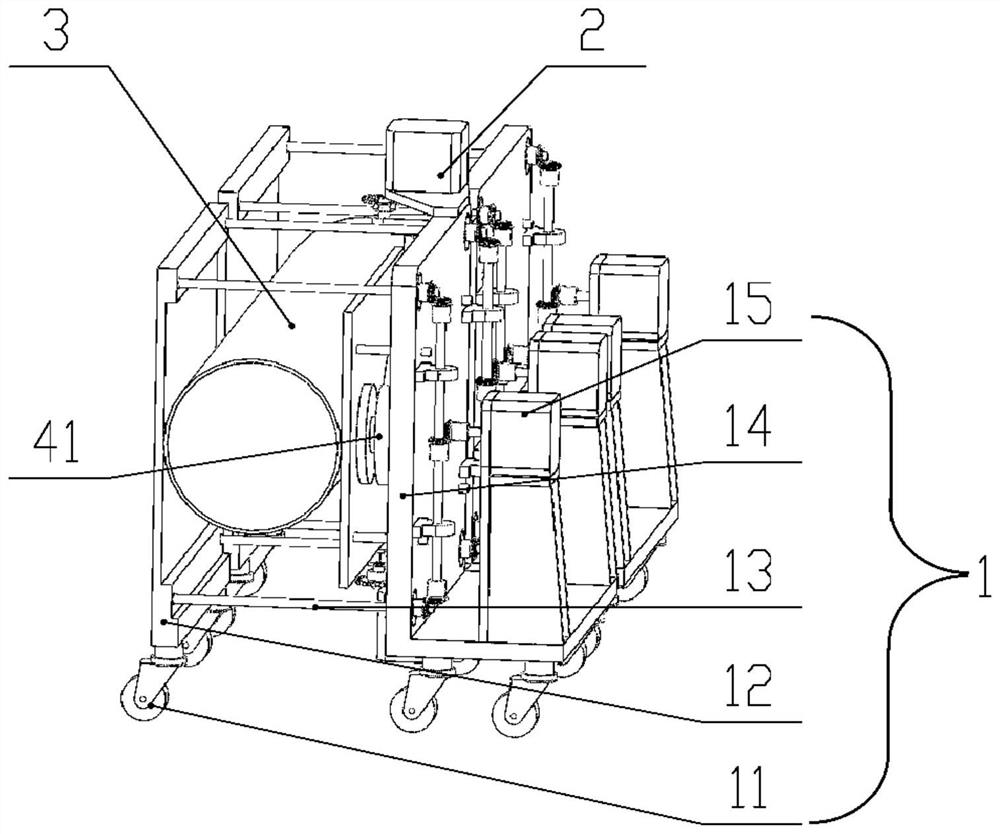
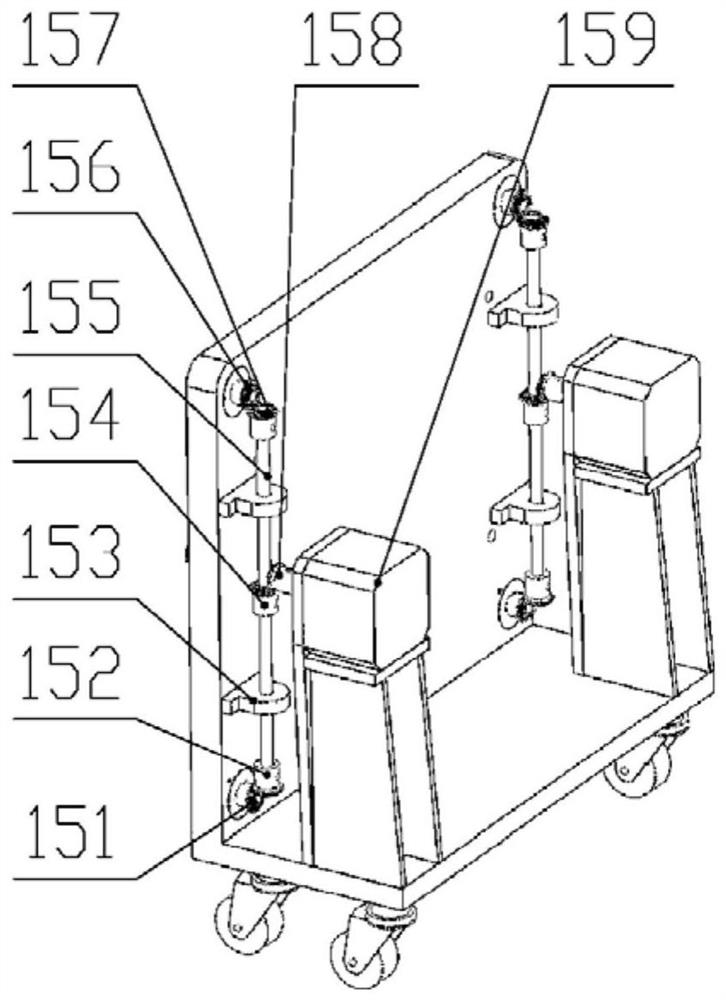
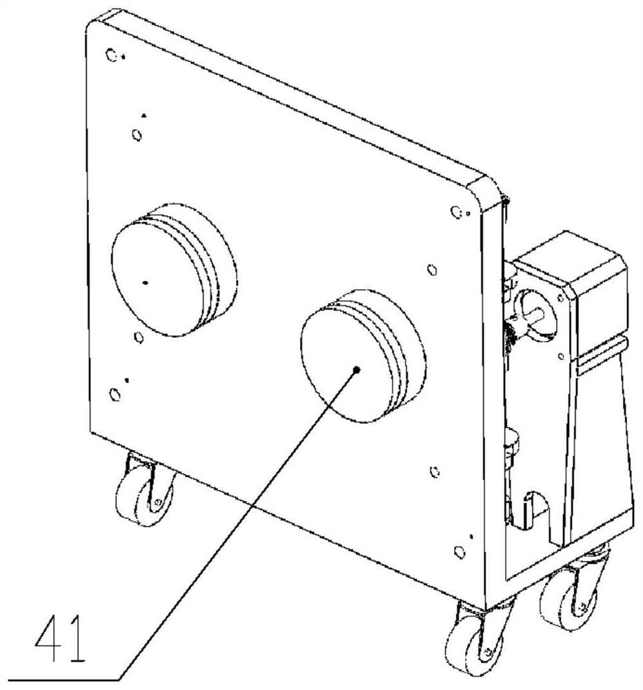
[0040] Such as figure 1 As shown, a thin-walled tube integrated test device for bending and stretching provided by this embodiment includes a flattening mechanism 1, a bending mechanism 2, and a sensor; the flattening mechanism 1 includes a pressing plate 12, a bearing plate 14, a screw mechanism 13, a transmission Mechanism 15, backing plate, bearing plate 14 is L-shaped member, and transmission mechanism 15 is fixedly installed on the right side of bearing plate 14, and pressing plate 12 is installed on the left side of bearing plate 14 movable by screw mechanism 13; Screw mechanism 13 comprises screw Rod, screw nut, the screw is fixedly installed on the pressure plate 12, the screw nut and the bearing plate 14 constitute a rotating pair, the screw passes through the bearing plate 14 through the screw nut; the screw nut and the screw constitute a ball screw transmission pair Or a roller screw transmission pair, the present embodiment is preferably a ball screw transmission p...

Embodiment 2

[0052] On the basis of Embodiment 1, the sensor also includes a displacement sensor. The displacement sensor is configured to detect the relative distance between the pressing plate 12 and the backing plate. The displacement sensor can be arranged between the pressing plate 12 and the backing plate or on the screw rod. In this embodiment Preferably, the displacement sensor is arranged on the screw rod.

Embodiment 3

[0054] On the basis of embodiment 1, the number of crushing mechanisms 1 is three, and the left, middle and right of the three crushing mechanisms 1 are arranged side by side at a time.


PUM


Abstract

The invention discloses a thin-walled tube bending and stretching integrated test device and method, which relate to the field of mechanical engineering technology testing, including a flattening mechanism, a bending mechanism, and a sensor; the flattening mechanism includes a pressing plate, a bearing plate, a screw mechanism, A transmission mechanism, the transmission mechanism is fixedly installed on the right side of the bearing plate, and the pressing plate is movably installed on the left side of the bearing plate through the screw mechanism; the number of the crushing mechanisms is greater than or equal to 2, corresponding The bending mechanism is respectively provided at the upper end and the lower end between the two crushing mechanisms; the bending mechanism includes a first connecting plate, a second connecting plate, a rotating shaft, and a bending transmission mechanism; the sensor includes a pressure sensor, torque sensor. The integrated test device of the present invention has simple structure, convenient use and maintenance, and can realize continuous tests of flattening, bending, folding and unfolding of large-diameter thin-walled pod rods and thin-walled round tubes, and record the mechanical state parameters during the whole test process .

Description

technical field [0001] The invention relates to the field of mechanical engineering technology tests, in particular to an integrated test device and method for compression, bending and expansion of thin-walled pipes. Background technique [0002] The space deployable structure is a structural system widely used in large spacecraft. Traditionally, mechanical hinge systems are mostly used. Mechanical hinge systems are mainly driven by motors. However, the disadvantages of mechanical hinge systems are complex mechanisms, heavy weight, and low deployment reliability. With the development of material science and technology, the space expandable structure based on the integration of material mechanism and structure has become a research hotspot and development trend. Using high-performance composite materials, through the elasticity or shape memory of the material, the material is folded on the ground and launched into orbit. Release elastic energy or store energy in thermal memor...

Claims


Application Information

Patent Timeline
Patent Type & Authority Patents(China)
IPC IPC(8): G01N3/02
Inventor 陈务军胡建辉赵兵房光强曹争利彭福军
Owner SHANGHAI JIAOTONG UNIV
Why Eureka
Try Eureka