Quick-split type box-shaped section steel concrete column-H-shaped steel concrete beam connection node

A technology for concrete columns and concrete beams, applied in the direction of columns, joists, girders, etc., can solve the problems of weakening the structural strength of box-shaped steel columns, decreasing the stability of box-shaped steel columns, and the large amount of welding work for connecting plates, etc. On-site construction efficiency, reduced on-site welding volume, and high production efficiency

Pending Publication Date: 2019-06-21
XI'AN UNIVERSITY OF ARCHITECTURE AND TECHNOLOGY
View PDF0 Cites 1 Cited by
  • Summary
  • Abstract
  • Description
  • Claims
  • Application Information

AI Technical Summary

Problems solved by technology

In the prior art, connection methods such as setting steel corbels, connecting plates, perforating steel column webs, and anchoring beam main reinforcement into columns are usually used to solve the problem of connecting nodes, but the existing connection methods will bring many problems, such as setting steel cattle The legs will produce a sudden change in section bearing capacity and stiffness at the end, which is prone to concrete extrusion damage, a large amount of on-site welding work for the connecting plate, high positioning accuracy requirements for perforation, and the stability of the box-shaped steel column after the hole is opened. decline, which weakens the structural strength of the box-shaped steel column, etc.

Method used


Image

  • Quick-split type box-shaped section steel concrete column-H-shaped steel concrete beam connection node
  • Quick-split type box-shaped section steel concrete column-H-shaped steel concrete beam connection node
  • Quick-split type box-shaped section steel concrete column-H-shaped steel concrete beam connection node

Examples


Embodiment Construction

[0026] The present invention is further described below in conjunction with accompanying drawing:

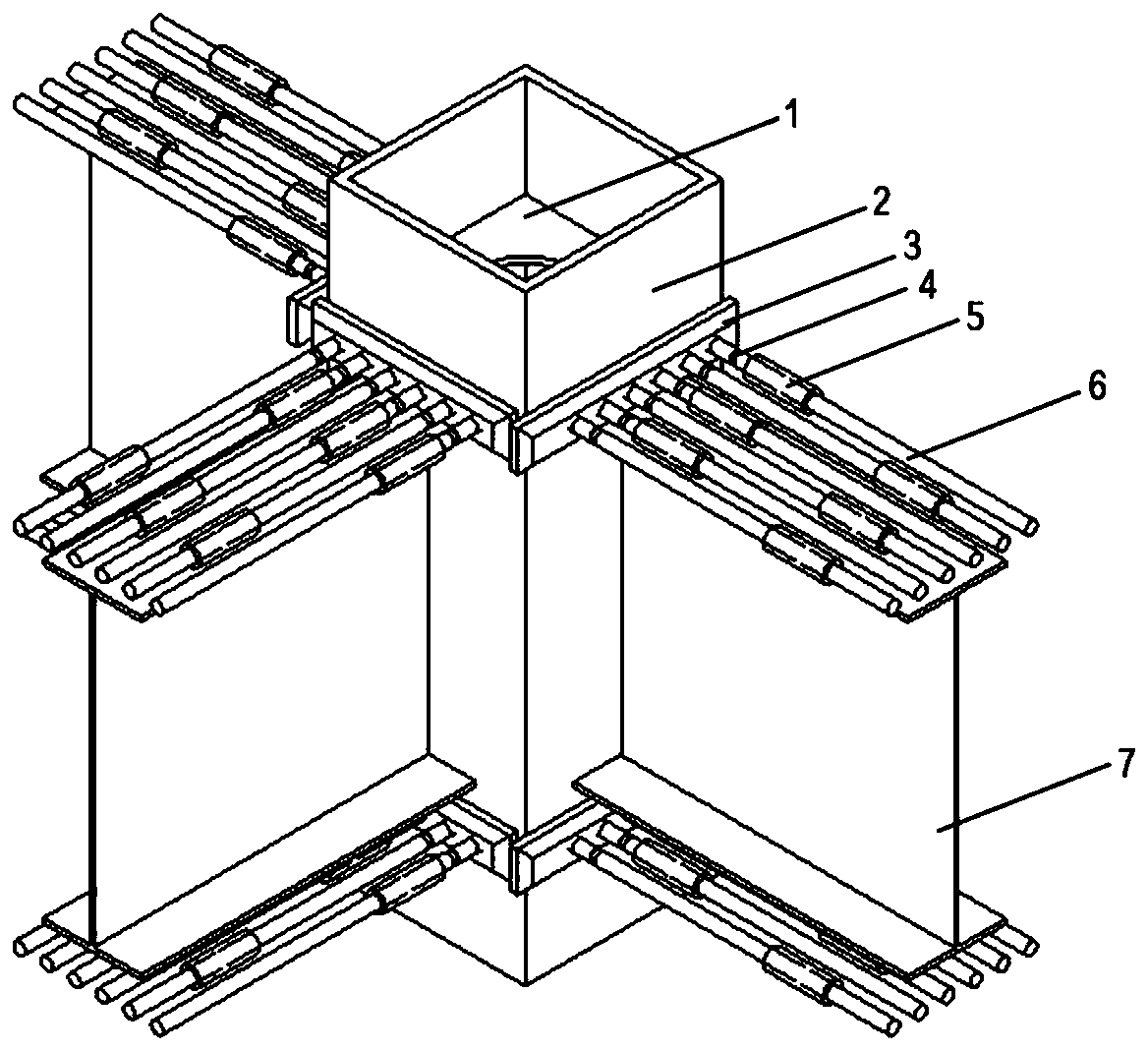
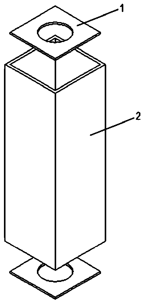
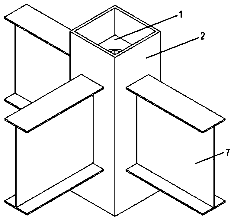
[0027] see Figure 1 to Figure 8 , a quick-assembled box-shaped steel concrete column-H-shaped steel concrete beam connection node, including box-shaped steel columns 2, H-shaped steel beams 7, connecting plates 3 and reinforcing ribs; several H-shaped steel beams 7 are vertically fixed on the box On the outer wall of the shaped steel column 2, connecting plates 3 are fixedly arranged on the side walls of the box-shaped steel column 2 above and below each H-shaped steel beam 7, and several threaded holes are arranged on the connecting plate 3, and all connecting plates 3 A number of reinforcing ribs are arranged vertically on the top. The number of H-shaped steel beams 7 is three.

[0028] The reinforcing ribs include double-ended studs 4, steel bar connectors 5 and steel bars 6; Connection, the other end of the double-ended stud 4 is threaded with the connecting plate 3; the...


PUM


Abstract

The invention relates to a quick-split type box-shaped section steel concrete column-H-shaped steel concrete beam connection node, comprising a box-shaped section steel column, H-shaped steel beams, connecting plates and reinforcing ribs, wherein the plurality of H-shaped steel beams are separately and vertically fixed on the outer side wall of the box-shaped section steel column; the connecting plates are fixedly arranged on the side wall of the box-shaped section steel column at the parts above and under all the H-shaped steel beams; the connecting plates are provided with a plurality of threaded holes; the plurality of reinforcing ribs are vertically arranged on the connecting plates. Compared with the traditional universal node for box-shaped section steel concrete beam columns, the quick-split type box-shaped section steel concrete column-H-shaped steel concrete beam connection node is produced in a way of connecting reinforcing steel bars with the connecting plates and welding the connecting plates with the box-shaped section steel column; by changing the lengths of studs, the requirement of misaligned connection of reinforcing steel bar joints is met, so that stress concentration is avoided. Furthermore, the percentage of the area of the reinforcing steel bar joints reaches 50%, so that superstrong connection is realized. The quick-split type box-shaped section steel concrete column-H-shaped steel concrete beam connection node is higher in connection efficiency, and improves the node bearing capacity and ductility.

Description

technical field [0001] The invention belongs to the technical field of beam-column connection nodes, in particular to a quick-assemble box-shaped steel concrete column-H-shaped steel concrete beam connection node. Background technique [0002] The box-shaped steel-concrete column composite structure has the dual advantages of steel structure and concrete structure. Compared with steel structure, it can save steel, increase the rigidity of components and buildings, and compared with concrete structure, it can reduce section weight and increase component ductility, etc. characteristics, so it is widely used in construction. However, in the actual construction process of the box-shaped steel concrete column structure, many problems will arise in the crossing of steel bars at the beam-column joints. In the prior art, connection methods such as setting steel corbels, connecting plates, perforating steel column webs, and anchoring beam main reinforcement into columns are usually ...

Claims


Application Information

Patent Timeline
Patent Type & Authority Applications(China)
IPC IPC(8): E04B1/24E04B1/58E04G21/14E04C3/04E04C3/32
Inventor 孙晓岭薛强刘瀚超王昊惠凡纪东昊刘哲龙
Owner XI'AN UNIVERSITY OF ARCHITECTURE AND TECHNOLOGY
Why Eureka
Try Eureka