
Pile driving barge and posture adjustment, positioning control and pile driving methods thereof

A technology for a piling ship and a piling device, which is used in attitude control, sheet pile wall, transportation and packaging, etc., can solve the problems of easy breaking, pile caps and hydraulic pile hammers falling into the sea, and safety problems, so as to avoid breaking. pile, the effect of improving safety and service life

Active Publication Date: 2019-06-21
JIANGSU UNIV OF SCI & TECH +1
View PDF7 Cites 18 Cited by
  • Summary
  • Abstract
  • Description
  • Claims
  • Application Information

AI Technical Summary

Problems solved by technology

[0004] However, at present, a large amount of work in the piling operation process is completed manually. Under the influence of wind, waves and currents, the piling ship cannot guarantee the stability of the hull during the piling process, and cannot meet the high-precision requirements of the position and inclination angle of the piling.
None of the existing methods for improving the stability of piling ships can solve the problem well. For example, in the patent ZL201410557626.2, the method and system for automatic balancing of large cargo ships with ballast function will be located in the lower balance cabin The water inside is pumped into the balance cabin at a higher place to maintain the balance of the hull, but the compensation lag of this method is particularly large; and a anti-wave piling ship as described in the patent ZL201420532754.7, although the longitudinal stability of the piling ship is improved, However, there is no control over the heave motion of the main deck; another example is a anti-wave piling ship described in patent ZL201420532727.
Therefore, in the current piling process, there are often different degrees of inclined pile problems, which are difficult to solve well.
[0005] In addition, during the pile group operation, the piling ship needs to move back and forth between the piling area and the pile hanging area. Controlling the movement of the hull by dragging or other methods cannot make the pile frame on the hull move accurately to the piling position, which cannot meet the needs of the hull. Bit accuracy requirements greatly affect the accuracy of piling
[0006] In view of the above two reasons, some areas that require precise piling to build offshore platforms often have to give up development
[0007] In addition, the existing piling ships still have the following problems: when the piling ship encounters sudden sea conditions, it needs to quickly take off and land the pile frame, and quickly drive away from the operation site to reduce equipment and personnel damage caused by sudden sea conditions. Lifting and landing mainly uses hydraulic pressure as the main power and the pulley block as the auxiliary power to realize the lifting and landing operation of the pile frame. This method is cumbersome to operate, and the process still requires manual assistance, which is inefficient and has safety problems
Cutting the pile lugs is done manually. Workers ride on a platform that can be raised and lowered along the pile frame to the height near the lugs, and use a cutting device to cut off the lugs, which is inefficient and has safety problems
In the piling operation, the occurrence of a slipping pile accident will cause huge losses, and there are safety problems. When the pile slipping occurs, the pile cap and the hydraulic pile hammer will drop rapidly and uncontrollably. Cap and hydraulic pile hammer crash into sea causing massive damage

Method used


Image

  • Pile driving barge and posture adjustment, positioning control and pile driving methods thereof
  • Pile driving barge and posture adjustment, positioning control and pile driving methods thereof
  • Pile driving barge and posture adjustment, positioning control and pile driving methods thereof

Examples


Embodiment Construction

[0153] Specific embodiments of the present invention will be described in detail below in conjunction with the accompanying drawings.

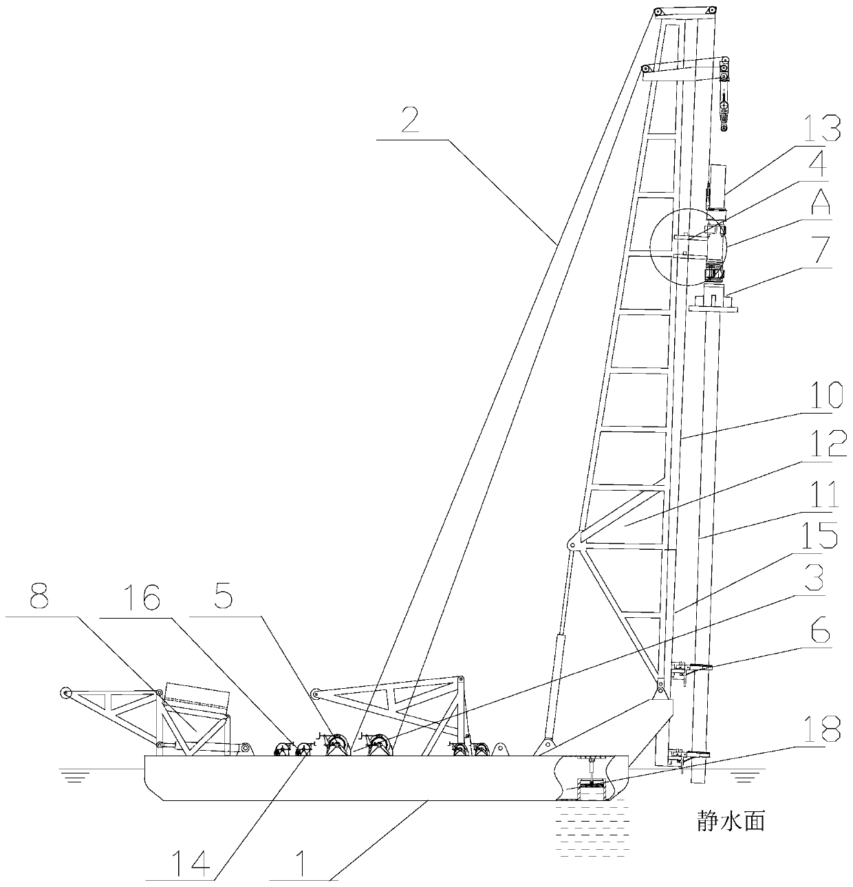
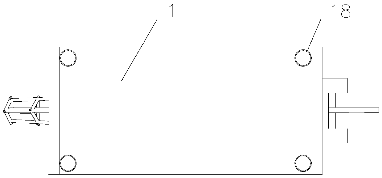
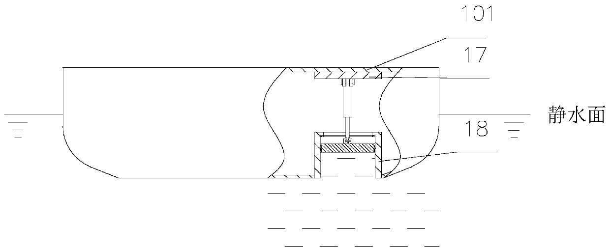
[0154] Such as Figure 1-8 And as shown in 38 and 39, a piling ship includes a hull 1, the four corners of the hull 1 are respectively provided with a buoyancy adjustment device, the lower surface of the deck 101 is connected with the buoyancy adjustment device, and the buoyancy adjustment device includes a buoyancy adjustment device arranged on the hull 1 The ballast water tank 18 and the connecting plate 17 provided on the lower surface of the deck 101, the connecting plate 17 is hinged with a propulsion device 182 arranged vertically downward, and the bottom of the ballast water tank 18 is provided with a through hole communicating with the outside world, The ballast water tank 18 is provided with a pressure water plate 181 on the liquid surface, and a sealing ring 185 is arranged between the pressure water plate 181 and the inner wall of t...


PUM


Abstract

A pile driving barge comprises a barge body, buoyancy adjusting devices are arranged at four corners of the barge body respectively, an upper scanner and a lower scanner for scanning vertical piles are arranged on the barge body, and GPS signal receivers are arranged at two different positions of the barge body; anchor machines for anchoring at least four different positions are arranged on the barge body; a pile frame is rotationally arranged on the barge body; the barge body is provided with an automatic pile frame lying device; a piling guide rail is arranged on the pile frame; a pile hammer is movably arranged on the pile driving guide rail; a first brake device for limiting the position of the pile hammer on the pile driving guide rail is arranged on the pile hammer, a transition roller is arranged on the upper portion of the pile frame, the upper portion of the pile hammer is connected with a winch arranged on the barge body through a steel wire rope, and a second brake device for braking by braking a winch roller to control the steel wire rope to pull the pile hammer is arranged on the barge body; and a pile cap is arranged on the pile hammer, a pile gripper for gripping thevertical pile is arranged on the lower portion of the pile frame. The invention further discloses a posture adjusting method, a positioning control method and a pile driving method of the pile driving barge.

Description

technical field [0001] The present invention relates to a piling ship and its control method, in particular to a piling ship and its posture adjustment method, positioning control method and piling method. Background technique [0002] The piling barge is a kind of offshore piling equipment. The piling barge is used to install the piles in the subsea soil layer. After the pilings are installed, wind power generation and other operating platforms can be installed on the pilings. With the demand for expanding opening up and in-depth development of coastal areas and the promotion of the country's strategic layout of the economic circle around the sea, water engineering projects in coastal areas are increasing. Ships are gradually developing in the direction of large-scale and automation. At the same time, the requirements for the accuracy and efficiency of piling ships in offshore pile foundation projects are constantly increasing. However, the construction of pile foundation ...

Claims


Application Information

Patent Timeline
Patent Type & Authority Applications(China)
IPC IPC(8): E02D7/06E02D13/04E02D13/06E02D13/10B63B35/00G05D1/08G06F17/50
CPCB63B35/00E02D7/06E02D13/04E02D13/06E02D13/10G05D1/08G06F30/20B63B39/03
Inventor 唐文献郭胜张建苏世杰王鑫尚勇志张铁陈赟常委锋刘琴王为民王月阳齐继阳
Owner JIANGSU UNIV OF SCI & TECH
Learn More