
Automobile automatic braking mechanism using vacuum booster and controlling method thereof

A vacuum booster and automatic braking technology, which is applied in the direction of brakes, brake transmissions, vehicle components, etc., can solve the problems of potential safety hazards in automobiles, slow pressurization of electronic stability control systems, large vehicle modifications, etc., to achieve braking Good effect, rapid braking, small structural changes

Pending Publication Date: 2019-06-21
JILIN UNIV
View PDF0 Cites 2 Cited by
  • Summary
  • Abstract
  • Description
  • Claims
  • Application Information

AI Technical Summary

Problems solved by technology

[0004] Although the feasibility of the above two advanced technologies has been verified, it can be found that although these two systems are new methods that can realize the automatic braking control of vehicles, the electronic stability control system (ESP) has a relatively slow boost and electronic stability. The hydraulic braking system (IBS) has a large modification to the vehicle, which makes the car a safety hazard

Method used


Image

  • Automobile automatic braking mechanism using vacuum booster and controlling method thereof
  • Automobile automatic braking mechanism using vacuum booster and controlling method thereof
  • Automobile automatic braking mechanism using vacuum booster and controlling method thereof

Examples


Embodiment Construction

[0058] The present invention will be further described in detail below in conjunction with the accompanying drawings, so that those skilled in the art can implement it with reference to the description.

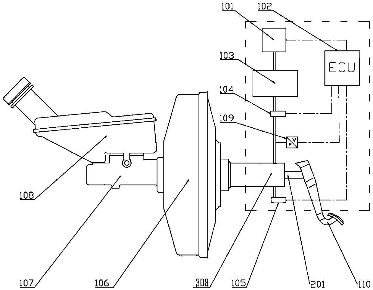
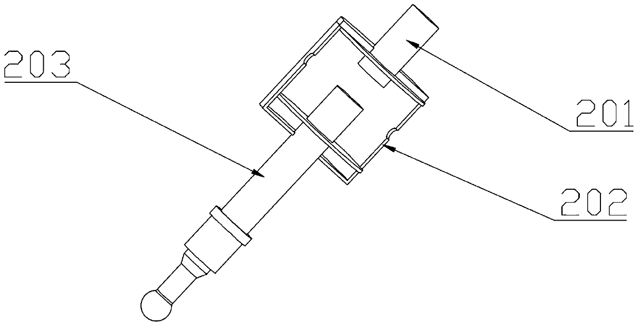
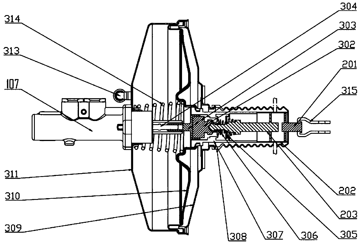
[0059] Such as Figure 1-5 As shown, the present invention provides an automatic braking mechanism utilizing a vacuum booster, including: a front housing 311, a rear housing 309, a master cylinder push rod 304, a spring diaphragm 310, a return spring 314, a push rod mechanism, a spring Mechanism, rear push rod 202, front push rod 201, intake valve 104, exhaust valve 105, automatic braking control unit 102.

[0060] The housing 106 of the vacuum booster includes a front housing 311 and a rear housing 309. The front housing 311 and the rear housing 309 are detachably connected. On the front housing 311, located at one end of the front housing, a vacuum tube 313 is connected. , The front housing 311 is connected to a vacuum pump through a vacuum tube to provide a vacuum for the...


PUM


Abstract

The invention discloses an automobile automatic braking mechanism using a vacuum booster, comprising a shell, a main cylinder, a main cylinder pushing rod, a linkage mechanism, a spring diaphragm, a rear pushing rod, a front pushing rod, a high-pressure cylinder and a controlling unit, wherein one end of the shell is communicated with a vacuum tube; the main cylinder penetrates through one end ofthe shell and is supported on the shell; one end of the main cylinder pushing rod is arranged in the main cylinder; one end of the linkage mechanism is arranged on the other end of the main cylinder pushing rod in a sleeving manner, and the linkage mechanism does reciprocating motion along the main cylinder pushing rod; the spring diaphragm fixedly sleeves the outside of the linkage mechanism andis fixedly connected with the shell at the same time; one end of the rear pushing rod is connected with the other end of the linkage mechanism; the front pushing rod is coaxially and oppositely arranged with the rear pushing rod at an interval; the high-pressure cylinder is arranged between the rear pushing rod and the front pushing rod; and the controlling unit is electrically connected with high-pressure cylinder. By starting an air intake mechanism, and pushing the rear pushing rod to move forward to start the braking mechanism, the automobile active braking is realized. The invention further provides a controlling method of the automobile automatic braking mechanism using the vacuum booster.

Description

technical field [0001] The invention relates to an automobile automatic braking mechanism using a vacuum booster and a control method thereof, belonging to the field of automobiles. Background technique [0002] With the increase of traffic accidents year by year, automobile safety technology has become a research hotspot. Passive safety technologies (such as airbags, safety belts, etc.) have mitigated accident injuries to a certain extent, but have not fundamentally solved the accidents. Therefore, the development focus of automotive safety technology is gradually shifting from passive safety to active safety. [0003] At present, automotive active safety technology has become increasingly mature. Traditional automotive active safety technologies are represented by vehicle stability control systems such as anti-lock braking system (ABS) and electronic stability control system (ESP). Driving system (ADAS) is getting more and more attention and application. As the executiv...

Claims


Application Information

Patent Timeline
IPC IPC(8): B60T13/52B60T13/72
Inventor 靳立强张荣林郭昊刘亚丽
Owner JILIN UNIV
Learn More