A ball mill automatic speed regulation system and method

An automatic speed regulation and ball mill technology, applied in grain processing, etc., can solve the problems of ball mill damage, slow processing efficiency, and inability to disassemble freely, and achieve the effects of increasing work efficiency, prolonging service life, and convenient operation

Active Publication Date: 2020-11-17
湖南山瑞重工科技有限公司
View PDF6 Cites 0 Cited by
  • Summary
  • Abstract
  • Description
  • Claims
  • Application Information

AI Technical Summary

Problems solved by technology

[0002] The ball mill is the key equipment for crushing the material after it is crushed. This type of grinding machine is filled with a certain number of steel balls in its cylinder as the grinding medium. It is widely used in cement, silicate products, new building materials , refractory materials, chemical fertilizers, black and non-ferrous metal beneficiation, and glass ceramics and other production industries; traditional ball mills do not have speed regulating devices and can only rotate uniformly, resulting in too slow processing efficiency and cannot be applied to various processing conditions; and traditional ball mills are integrated The device cannot be disassembled freely, which makes it difficult to clean and replace the ball mill components, which is not conducive to user use. At the same time, the traditional ball mill has no protection device, and the ball mill itself is prone to vibration when it is working, causing damage to the ball mill, which is not conducive to protecting the ball mill and reducing the service life of the ball mill; for These defects, it is necessary to design a ball mill automatic speed regulation system and method

Method used


Image

  • A ball mill automatic speed regulation system and method
  • A ball mill automatic speed regulation system and method
  • A ball mill automatic speed regulation system and method

Examples


Embodiment Construction

[0027] The following will clearly and completely describe the technical solutions in the embodiments of the present invention with reference to the accompanying drawings in the embodiments of the present invention. Obviously, the described embodiments are only some, not all, embodiments of the present invention. Based on the embodiments of the present invention, all other embodiments obtained by persons of ordinary skill in the art without making creative efforts belong to the protection scope of the present invention.

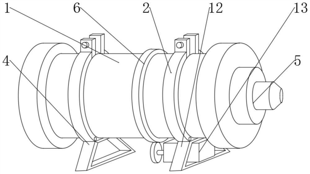
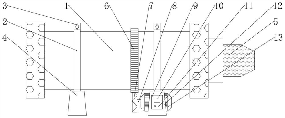
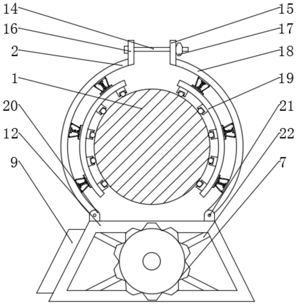
[0028] see Figure 1-6, the present invention provides a technical solution: a ball mill automatic speed regulation system, including a ball mill body 1, a first semicircular clamp plate 2, a bolt hole 3, a first base 4, a feed port 5, a gear ring 6, and a rotating gear 7 , rotating shaft 8, speed regulating shell 9, touch screen 10, adjusting knob 11, second base 12, three-phase motor 13, first bolt 14, first fixing block 15, second fixing block 16, nut sleev...


PUM


Abstract

The invention discloses a ball grinder automatic speed adjusting system and method. The system comprises a ball grinder body, a first semi-circular clamping plate, a bolt hole, a first base, a rotating shaft, and a speed adjusting shell; a feeding opening is formed is formed in one end of the ball grinder body, the first base is arranged on one side of the bottom of the ball grinder body, a secondbase is arranged on the other side of the bottom of the ball grinder body, the second base is located on one side of the first base, a fixed frame is fixed into the second base through a screw, a three-phase motor is fixed to the center of the fixed frame through a screw, and is located in the second base, and one end of the three-phase motor is sleeved with the rotating shaft. The ball grinder automatic speed adjusting system is simple in structure, the material size and kind are input, a data analysis module analyzes the rotating speed needed by the motor, an instruction is issued, throughan instruction output module, the three-phase motor is controlled to rotate, the aim of adjusting the rotating speed of the ball grinder body is achieved, work efficiency is greatly improved, and useby a user is convenient.

Description

technical field [0001] The invention relates to the technical field of ball mills, in particular to an automatic speed regulation system and method for ball mills. Background technique [0002] The ball mill is the key equipment for crushing the material after it is crushed. This type of grinding machine is filled with a certain number of steel balls in its cylinder as the grinding medium. It is widely used in cement, silicate products, new building materials , refractory materials, chemical fertilizers, black and non-ferrous metal beneficiation, and glass ceramics and other production industries; traditional ball mills do not have speed regulating devices and can only rotate uniformly, resulting in too slow processing efficiency and cannot be applied to various processing conditions; and traditional ball mills are integrated The device cannot be disassembled freely, which makes it difficult to clean and replace the ball mill components, which is not conducive to user use. A...

Claims


Application Information

Patent Timeline
Patent Type & Authority Patents(China)
IPC IPC(8): B02C17/10B02C23/04B02C25/00
Inventor 刘忻涛刘湘杨科于铁根雷杰
Owner 湖南山瑞重工科技有限公司
Why Eureka
Try Eureka