
Laser cutting head comprosing a body made of two parts, being linked together by a flexible member

A technology of laser cutting head and body, which is applied in the direction of laser welding equipment, welding/cutting auxiliary equipment, auxiliary devices, etc.

Pending Publication Date: 2019-06-18
EJMA JANUSZ MARCIN POWER TECH
View PDF10 Cites 0 Cited by
  • Summary
  • Abstract
  • Description
  • Claims
  • Application Information

AI Technical Summary

Problems solved by technology

What's more, the heating of the optics can also create additional unwanted hot lenses or other disturbances on the heated lens, which means that heated gas on the lens can also adversely affect the quality of the beam

Method used


Image

  • Laser cutting head comprosing a body made of two parts, being linked together by a flexible member
  • Laser cutting head comprosing a body made of two parts, being linked together by a flexible member
  • Laser cutting head comprosing a body made of two parts, being linked together by a flexible member

Examples


Embodiment Construction

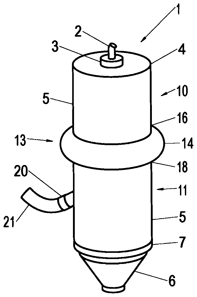
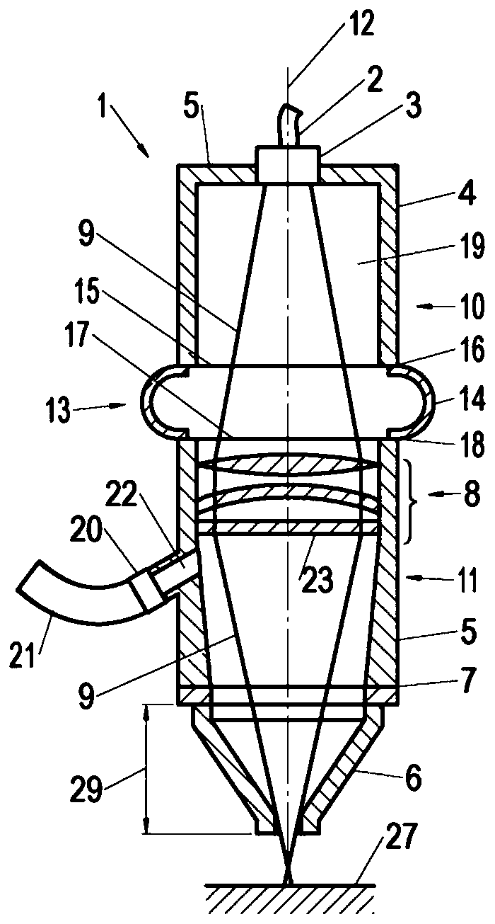
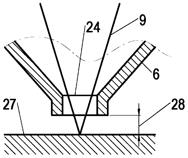
[0054] figure 1 and figure 2 Shown respectively are a perspective view and a cross-sectional view of a laser cutting head 1 comprising: a laser light source 3 connected to an optical fiber 2 and positioned at a first end 4 of a body 5; a nozzle 6, the nozzle 6 Located at the other end 7 of the body 5; the optical system 8, which is located inside the body 5, between the laser light source 3 and the nozzle 6, so that during operation the laser beam 9 passes from the laser light source 3 through the optical system 8 and then through nozzle6.

[0055] The body 2 comprises: a first part 10 of the body 5 integrated with the laser light source 3 and a second part 11 of the body 5 integrated with the optical system 8 and the nozzle 6 . The first part 10 of the body 5 is slidable relative to the second part 11 of the body 5 along and through the optical axis 12 of the head 1 so as to provide a second position of the first part (10) of the body (5) relative to the body (5). The ran...


PUM


Abstract

The present application relates to a laser cutting head (1), which comprises a body (2), a laser light source (3) located at a first end (4) of the body (5), a nozzle (6) located at a other end (7) ofthe body (5), an optical system (8) located inside the body (5) between the laser light source (3) and the nozzle (6). The body (2) comprises at least two parts (10, 11), which are slidable relativeto each other in such a way that, due to their reciprocal displacement, the mutual position of the laser light source (3) and / or the nozzle (6) and / or the optical system (12) can be changed, so that the geometry of the laser beam (9) inside the body (2) can be changed during use to achieve the desired parameters of the focus of the laser beam (9) on the surface of the workpiece (27).

Description

technical field [0001] The object of the invention is a laser cutting head, in particular for cutting metal parts, and a laser cutter comprising such a cutting head. Background technique [0002] Laser cutting heads are known for laser cutters, which use a laser beam and compressed gas to cut metal sheets. Such cutting heads include the optics necessary to focus the laser beam at the proper location on the workpiece surface. [0003] Chinese utility model patent CN202607091U discloses a tiltable laser cutting head with adjustable focus. In the lens assembly of the head, there is a mirror with variable curvature and it is connected to the lens barrel in a mechanical adjustment mode. This oscillating laser cutting head with laser beam focusing function can achieve fast zooming according to different laser processing requirements, and has automatic head swing, which can process trapezoidal seams with high efficiency and high quality. Another Chinese utility model patent CN20...

Claims


Application Information

Patent Timeline
IPC IPC(8): B23K37/02B23K37/04B23K26/046B23K26/08B23K26/14B23K26/38
CPCB23K37/0235B23K37/0408B23K26/0884B23K26/1476B23K26/1482B23K26/1488B23K26/38B23K26/046B23K26/08B23K26/14B23K31/10B23K26/0643
Inventor 雅努什·埃吉玛
Owner EJMA JANUSZ MARCIN POWER TECH
Learn More