
Regenerative catalytic oxidizer for treating VOCs (Volatile organic compounds) waste gas

A catalytic oxidizer and heat storage technology, applied in catalyst regeneration/reactivation, physical/chemical process catalysts, chemical instruments and methods, etc., can solve catalyst burning, catalyst damage, and inability to effectively control the operating temperature of high-temperature oxidation reaction chambers, etc. question

Inactive Publication Date: 2019-06-18
张荣兴
View PDF19 Cites 2 Cited by
  • Summary
  • Abstract
  • Description
  • Claims
  • Application Information

AI Technical Summary

Problems solved by technology

If the concentration of VOCs is high, the excess energy cannot be effectively discharged from the regenerative catalytic oxidation system (RCO), and the operating temperature of the high-temperature oxidation reaction chamber cannot be effectively controlled, and the RCO may run out of temperature control, causing the catalyst to burn or cause an explosion risk
In recent years, there have been many cases of explosion or incineration of regenerative catalytic oxidation systems (RCO) in the world, mainly due to the mistaken introduction of high-concentration VOCs exhaust gas into regenerative catalytic oxidation systems (RCO). In the case of improper supply adjustment, deflagration (Deflagration) or detonation (Detonation) phenomenon occurs or over-temperature operation leads to catalyst damage

Method used


Image

  • Regenerative catalytic oxidizer for treating VOCs (Volatile organic compounds) waste gas
  • Regenerative catalytic oxidizer for treating VOCs (Volatile organic compounds) waste gas
  • Regenerative catalytic oxidizer for treating VOCs (Volatile organic compounds) waste gas

Examples


Embodiment Construction

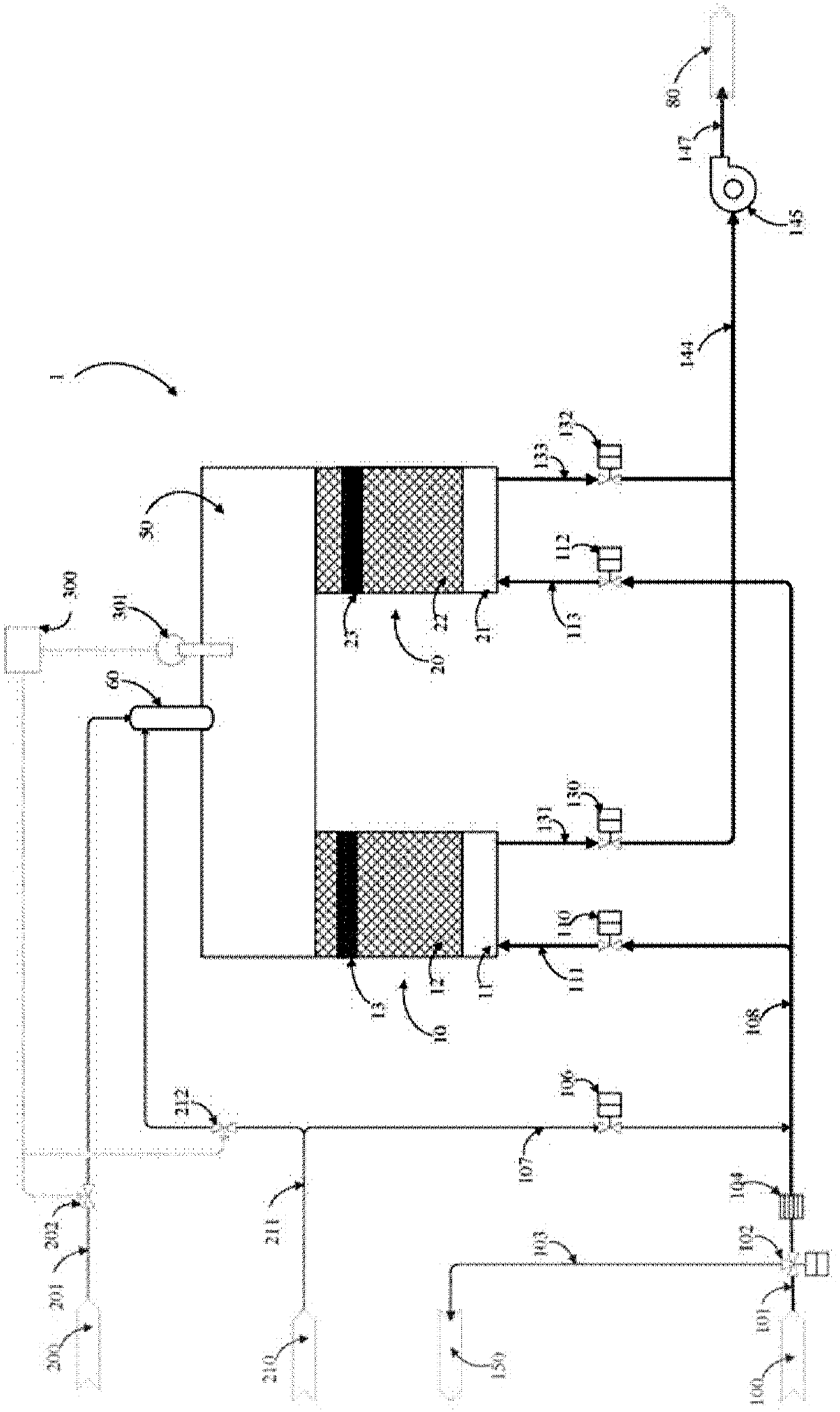
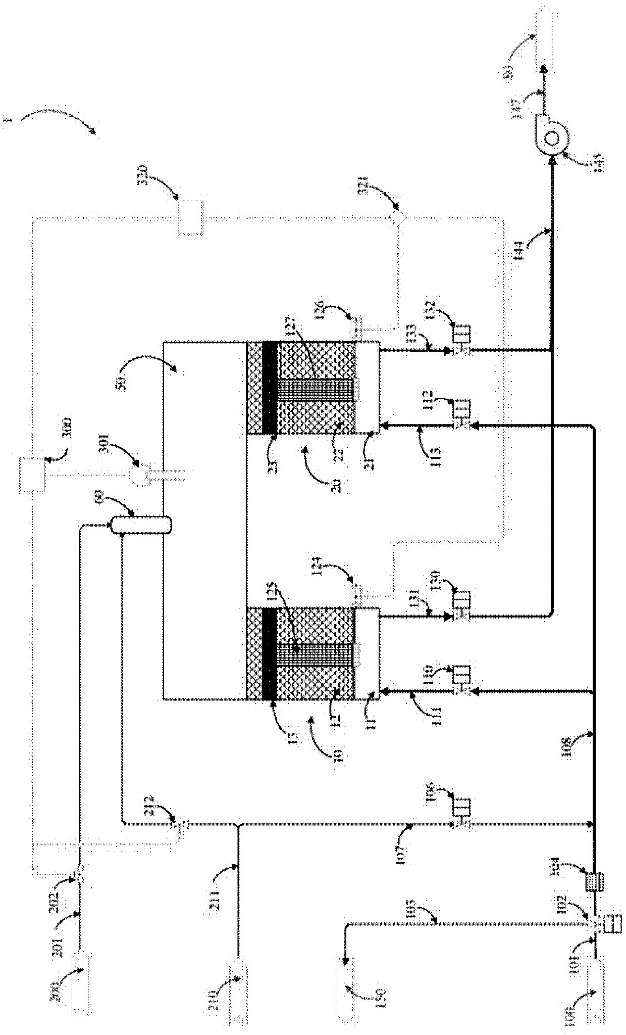
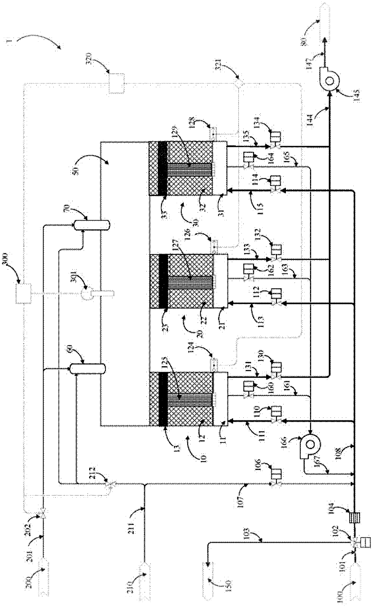
[0093] In order to achieve the above effects, the present invention provides a regenerative catalytic oxidizer 1 capable of treating VOC exhaust gas, which contains at least two catalytic regenerators, a high-temperature oxidation reaction chamber and an over-temperature logic for the high-temperature oxidation reaction chamber In the controller, there is a porous heat storage bed formed by stacking porous materials in the catalytic heat storage chamber, a porous catalyst bed above the porous heat storage bed, the high temperature oxidation reaction chamber is located above the catalytic heat storage chamber and combined with the catalytic heat storage chamber, and In the porous heat storage bed, some porous materials use materials with large porosity and low heat capacity to form the cold bypass fast channel inside the catalytic regenerator, and the cold bypass fast channel in the catalytic regenerator is equipped with automatic temperature control. Flow regulating valve and h...


PUM


Abstract

The invention provides a regenerative catalytic oxidizer for treating VOCs (Volatile organic compounds) waste gas. The regenerative catalytic oxidizer comprises two or more catalytic regenerators, a high-temperature oxidizing reaction chamber, and an overtemperature logic controller; a porous regenerative bed stacked by porous materials are arranged in each catalytic regenerator; a porous catalystbed is arranged above each porous regenerative bed; the high-temperature oxidizing reaction chamber is arranged above the catalytic regenerators, and is combined with the catalytic regenerators; partof the porous materials in each porous regenerative bed adopt materials with large porosity and low thermal capacity to form gas cold by-pass fast channels inside the regenerative groove; and flow regulating valves controlled by the overtemperature logic controller are arranged at the bottom of the gas cold by-pass fast channels. When temperature rises because the concentration of the VOCs wastegas exceeds a limiting value, the overtemperature logic controller is utilized to control the flow regulating valves; part of the VOCs waste gas is guided to enter the high-temperature oxidizing reaction chamber through the gas cold by-pass fast channels; and the operating temperature of the high-temperature oxidizing reaction chamber is regulated and controlled, so as to avoid an overtemperatureaccident of a system.

Description

technical field [0001] The main purpose of the present invention is to provide a regenerative catalytic oxidizer (Regenerative Catalytic Oxidizer, RCO) for treating VOC exhaust gas, which is characterized in that a cold bypass fast channel and a flow control valve are arranged in the catalytic regenerator chamber, and the Oxidation reaction chamber over-temperature logic controller, so that part of the VOCs exhaust gas can be maintained at a lower temperature and directly enter the high-temperature oxidation reaction chamber, which can completely solve the high temperature that often occurs when the concentration of VOC exhaust gas exceeds the limit of the regenerative regenerative catalytic oxidizer (RCO). Oxidation reaction chamber overheating and explosion problems. Background technique [0002] Volatile Organic Compounds (Volatile Organic Compounds, VOCs) are one of the common air pollutants in the industry, and their main sources are chemical plants, petrochemical indus...

Claims


Application Information

Patent Timeline
Patent Type & Authority Applications(China)
IPC IPC(8): B01D53/86B01D53/72B01D53/88B01D53/75B01J38/02
Inventor 张荣兴
Owner 张荣兴
Learn More